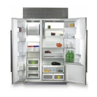
Planning
.
Information
Before moving ahead with
any planning you should be
aware of the basic require-
ments for the installation
of a built-in Sub-Zero. The
drawings in Figures 1 and 2
illustrate the finished rough
in dimensions, electrical
and plumbing locations and
minimum door clearance for
all units.
(with
leve/ers
in)
(FOOTNOTE: When using
frameless
cabinets, you
mu.9
add space
to
the
finished rough opening
to
allow for side mainframe overlap
to
ensure cabinet and Sub-Zero doors open properly. This space
will fluctuate depending on
the
installation and overall visual appearance you are
trying
to
achieve.)
(FOOTNOTE: When
insta//ing
cabinets
with
six inch bases, add
two
inches
to
the
minimum height
detailed above, if you
want
to
make
Me
base of
the
Sub-Zero even
with
the
cabinets.)
Locate Electrical
Outlet within Top
Shaded Area
501F Water Supply
within Bottom
Shaded Area
6”
Locate Electrical
Outlet within Top
Shaded Area
B
D
Locate Water Supply
withIn
Bottom
Shaded Area
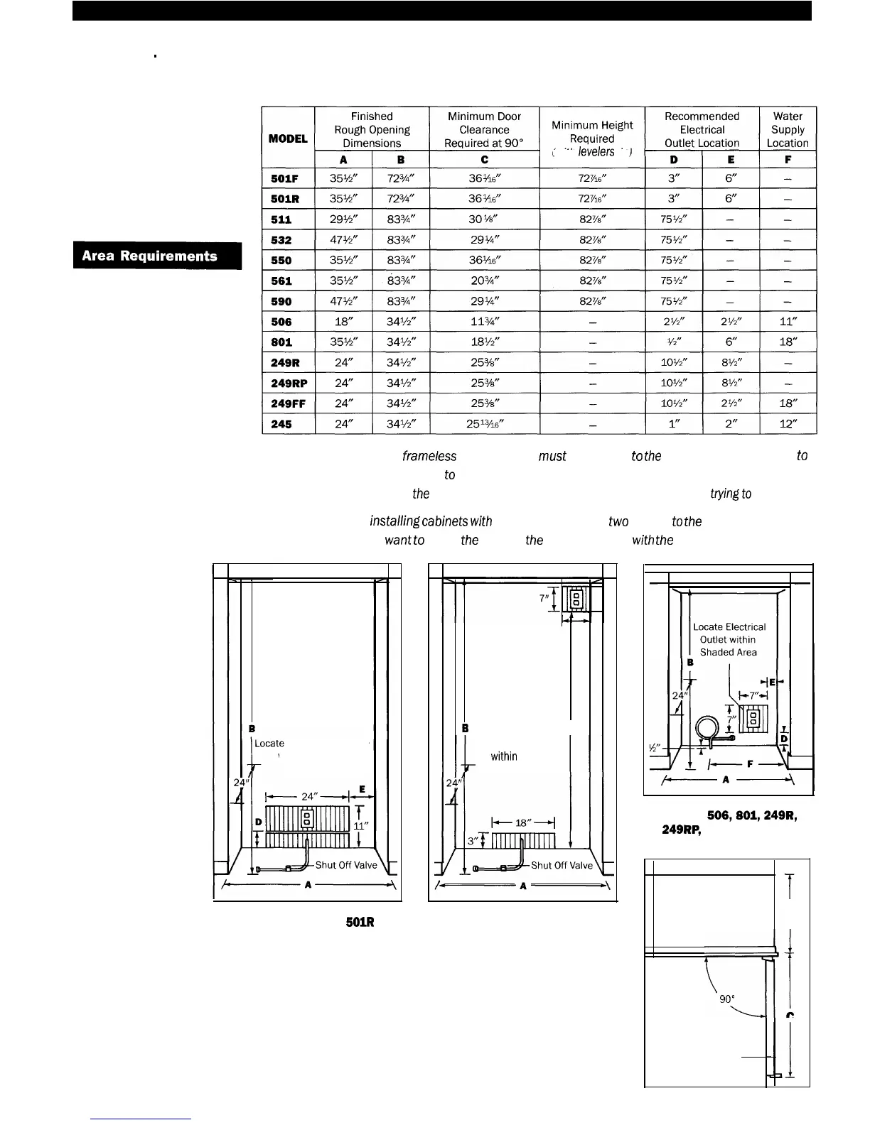
Models 501F and
5OlR
Figure 1
Models 511, 532,550,
561 and 590
Figure 2
l-l-7
Locate Electrical
Outlet within
Shaded Area
-
Models 506,601,249R,
249RP,
249FF and 245
23%”
Behind
Frame
iLJt
90°
C
Door