Do you have a question about the Sub-Zero 685-2 and is the answer not in the manual?
Critical safety precautions and warnings for operating and servicing the unit.
Contact information and procedures for obtaining technical support and service.
Details on product warranties, including duration and coverage for different components.
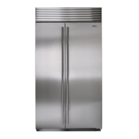
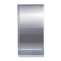
Overview of various 600-2 Series models and their specific features and finishes.
Key factors and potential issues to consider for proper unit installation.
Procedure for installing anti-tip hardware to prevent unit tipping.
Steps for ensuring the unit is properly leveled for optimal operation and door sealing.
Instructions on adjusting doors for proper alignment, sealing, and appearance.
Definitions of terms and descriptions of components within the electronic control system.
How to perform basic operations like turning the unit on/off and adjusting temperature settings.
Explanation of how the system monitors, regulates, and displays compartment temperatures.
Procedures for using the control panel for troubleshooting and diagnostics.
Guidelines and procedures for servicing the HFC-134a refrigerant sealed system.
Essential rules and precautions for handling and working with 134a refrigerant.
Step-by-step procedures for repairing common sealed system problems.
Explanation of the refrigerant flow and the role of each component in the sealed system.
Specifications and diagrams illustrating air flow paths and fan blade spacing for various models.
Overview of the icemaker system, its components, and basic operation.
Detailed descriptions of each component within the icemaker assembly.
Step-by-step explanation of the icemaker's operational cycle through electrical schematics.
Procedures for accessing and removing external cosmetic and mechanical components.
Steps for accessing and removing internal refrigerator compartment components.
Procedures for accessing and removing sealed system components like the filter-drier and compressor.
Detailed instructions for removing the electronic control board for diagnosis or replacement.
Guide on interpreting and using error codes for diagnosing unit malfunctions.
A table listing error codes, their indications, and associated troubleshooting actions.
Instructions on how to navigate and utilize the general troubleshooting guide based on problem descriptions.
Tables providing normal operating pressures and temperature/pressure correlations for sealed system diagnostics.
Detailed technical data, including charge, pressures, and component specifications for the 601R-2 model.
Technical data for the 611-2 model, covering charge, pressures, and component details.
Technical specifications for the 632-2 model, including charge, pressures, and component data.
Technical data for the 685-2 model, detailing charge, pressures, and component specifications.
Technical data for the 695-2 model, detailing charge, pressures, and component specifications.
Detailed wiring diagram for the 601R-2 model, showing electrical connections and components.
Wiring diagram for the 611-2 and 650-2 models, detailing electrical connections.
Wiring diagram for the 632-2 and 642-2 models, illustrating the electrical system layout.
Wiring diagram for the 685-2 and 695-2 models, illustrating electrical connections.
| Brand | Sub-Zero |
|---|---|
| Model | 685-2 |
| Category | Refrigerator |
| Language | English |