Integrated
Integrated
(700-
(700-
3
3
T
T
ALL)
ALL)
Series
Series
General Information
1-3
#3758412 - Revision B - December, 2006
Section 1 - General Information 1-1
Introduction ....................................................................... 1-2
Important Safety Information ............................................ 1-2
Technical Assistance ........................................................ 1-2
Table of Contents ............................................................. 1-3
Warranty Information ........................................................ 1-5
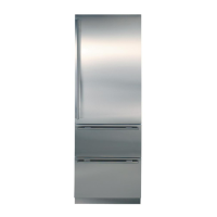
Model Description ............................................................. 1-6
Section 2 - Installation Information 2-1
Installation Considerations ............................................... 2-2
Unit leveling ................................................................. 2-2
Door & Drawer Adjustment ........................................... 2-3
Door Stop Adjustment .................................................. 2-3
Dual Unit Installation .................................................... 2-4
Section 3 - Electronic Control System Information 3-1
Terminology & Component Descriptions .......................... 3-2
Basic Electronic Control System ....................................... 3-3
Control Board Layout & Summary Table ......................... 3-4
Control Panel Layout ....................................................... 3-5
Basic Electronic Control Input Operations ....................... 3-5
Unit ON/OFF ................................................................ 3-5
Adjusting Set-Point (Temp. Adjustment) ...................... 3-6
Icemaker System ON/OFF ........................................... 3-6
Door Ajar Alarm Feature ON/OFF ................................ 3-6
Unique Electronic Control Input Operations .................... 3-7
Temperature Units Selection Mode .............................. 3-7
Sabbath Mode .............................................................. 3-8
Showroom Mode .......................................................... 3-8
Manual Zone Disable Mode .......................................... 3-9
Manual Freezer Evaporator Defrost ............................. 3-9
Functions of the Electronic Control System ................... 3-10
Supply Power to the Lighting System ........................ 3-10
Monitor, Regulate & Display Compartment Temp’s ..... 3-11
Control Variable Speed Compressor (700TF/I-3) ........ 3-12
Control Condenser Fan Run ....................................... 3-13
Refrigerator “Fan-Assisted Off-Cycle Defrost” ............. 3-14
Freezer “Adaptive Defrost” .......................................... 3-15
Monitor Compressor Run, Display Service ................. 3-16
Monitor Speed Signal to Variable Speed Comp.,
Display Service (700TF/I-3) ......................................... 3-17
Monitor Ice Making System, Display Service .............. 3-18
Possible Error Indicators ................................................ 3-19
700TC/I-3 & 736TC/I-3 ................................................. 3-19
700TR-3 & 736TR-3 .................................................... 3-20
700TF/I-3 ..................................................................... 3-21
Troubleshooting Input Operations ................................... 3-22
Diagnostic Mode ........................................................ 3-22
Thermistor Location Code Tables ........................... 3-23
Diagnostic Mode Indicators ...................................... 3-23
Error Code Table ...................................................... 3-24
Clearing Error Codes ................................................ 3-24
Manual Component Activation Mode ........................... 3-25
Temperature Log Recall Mode ................................... 3-26
Compartment Temp. History Only ............................ 3-26
Compartment & Evaporator Temp. History .............. 3-27
Possible Event Indicators ..................................... 3-28
Temperature Log Index Chart ................................ 3-29
Section 4 - Sealed System Information 4-1
HFC-134a Refrigerant Service Information ...................... 4-2
General Rules for Working with 134a Refrigerant ........ 4-2
Sealed System Repair Procedures .............................. 4-3
Sealed System Operation ................................................ 4-4
Sealed System Refrigerant Flow Diagrams ..................... 4-6
Models 700TC/I-3 & 736TC/I-3 ...................................... 4-6
Models 700TR-3 & 736TR-3 .......................................... 4-7
Model 700TF/I-3 ............................................................ 4-7
Section 5 - Air Flow & Fan Blade Spacing 5-1
Models 700TC/I-3 & 736TC/I-3 .......................................... 5-2
Models 700TR-3 & 736TR-3 .............................................. 5-3
Model 700TF/I-3 ................................................................ 5-3
Section 6 - Icemaker Information
6-1
Modular Icemaker ........................................................... 6-2
Modular Icemaker Operation ...................................... 6-2
Additional Icemaker Operation Notes ......................... 6-3
What Happens During Ejector Blade Rotation ............ 6-3
Modular Icemaker Test Procedures ................................ 6-4
Voltage Tests ................................................................ 6-4
Continuity Tests & Thermostat Inspection ................... 6-4
Water Fill Adjustment ...................................................... 6-5
Icemaker Disassembly .................................................... 6-5
Module/Motor Assembly ............................................. 6-5
Mold/Heater Assembly ............................................... 6-5
Ejector Blades and/or Ice Stripper .............................. 6-5
Icemaker Thermostat ................................................. 6-5
Section 7 - Component Access and Removal 7-1
Component Access and Removal ............................ 7-2
WARNINGS & CAUTIONS ................................................ 7-2
Exterior Cosmetic and Mechanical Components ......... 7-3
Kickplate/Grille .............................................................. 7-3
Side Molding Strip .......................................................... 7-3
Upper Compartment Light Switch and Fan Switch ........ 7-3
Drawer Assembly .......................................................... 7-4
Door & Drawer Gasket ................................................. 7-4
Door Assembly ............................................................. 7-5
Upper and Lower Hinge Assembly ................................ 7-5
TABLE OF CONTENTS
Page #
Page #