Do you have a question about the Sub-Zero 700TC-3 and is the answer not in the manual?
Covers the integrated 700-3 Tall series appliances.
Crucial safety warnings and precautions for using the manual.
Information on how to contact Sub-Zero for service support and inquiries.
Overview of the 2, 5, and 12-year residential and non-residential warranties.
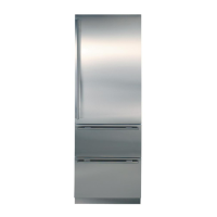
Brief descriptions and illustrations of the 700-3 Tall series models covered.
Common installation issues and best practices for a proper setup.
Steps for adjusting doors and drawers for proper alignment and sealing.
Instructions for installing multiple units side-by-side, including dual unit heaters.
Definitions of terms and descriptions of components in the electronic control system.
Overview and diagram of the fundamental electronic control system.
Explanation of the control panel interface and its input operations.
Describes advanced operations like Temperature Unit Selection and Sabbath Mode.
Details on how the system manages lighting, temperature, fans, and defrost cycles.
Explains LCD error codes and indicators for diagnosing unit problems.
Detailed steps for resolving specific error codes indicated by the system.
Procedures for accessing diagnostic data and temperature history for troubleshooting.
Rules and procedures for servicing systems with 134a refrigerant.
Step-by-step instructions for common sealed system repair issues.
Fundamental roles of compressor, condenser, and filter-drier in the sealed system.
Visual representations of refrigerant flow for different 700-3 series models.
Diagrams illustrating airflow and correct fan blade spacing for specific models.
Diagrams illustrating airflow and correct fan blade spacing for specific models.
Diagrams illustrating airflow and correct fan blade spacing for specific models.
Information on icemaker models used and general system operation.
Details on the operation, testing, and disassembly of the modular icemaker.
Descriptions of components for MidSouth and Japan-Servo icemakers.
Explanation of the ice making cycle phases for specific icemaker types.
Procedures for manually stopping, starting, and adjusting the icemaker fill level.
Guide to identifying and resolving common icemaker problems and faults.
General procedures and safety notes for accessing and removing unit components.
Critical safety warnings and precautions before servicing components.
Instructions for removing exterior parts like kickplates, molding, and switches.
Procedures for accessing and removing internal components like shelves, lights, and boards.
Steps for removing sealed system parts like evaporators, filter-driers, and compressors.
Guide on interpreting and using error codes for diagnosing issues.
A comprehensive table listing error codes and their corresponding resolution actions.
Instructions for navigating and utilizing the general troubleshooting guide.
Tables for normal operating pressures and diagnostic indicators for the sealed system.
Table correlating evaporator temperatures with sealed system low-side pressures.
Procedure for testing the integrity and continuity of the control panel and ribbon cable.
Steps for testing and correcting door closing issues related to hinges.
Specifications, pressures, and component data for the 700TC/I-3 model.
Specifications, pressures, and component data for the 700TR-3 model.
Specifications, pressures, and component data for the 700TF/I-3 model.
Specifications, pressures, and component data for the 736TC/I-3 model.
Specifications, pressures, and component data for the 736TR-3 model.
Detailed wiring diagram for the 700TC-3 model, showing component connections.
Electrical schematic illustrating the flow of current for the 700TC-3 model.
Detailed wiring diagram for the 700TR-3 model, showing component connections.
Electrical schematic illustrating the flow of current for the 700TR-3 model.
Detailed wiring diagram for the 700TF/I-3 model, showing component connections.
Electrical schematic illustrating the flow of current for the 736TC/I-3 model.
Electrical schematic illustrating the flow of current for the 736TR-3 model.
| Width | 36 inches |
|---|---|
| Height | 84 inches |
| Cooling System | Dual Refrigeration |
| Finish | Stainless Steel |
| Energy Star Rated | Yes |
| Controls | Electronic |
| Lighting | LED |
| Door Style | French Door |
| Energy Star Certified | Yes |
| Ice Maker | Yes |
| Water Dispenser | No |
| Type | Refrigerator |
| Product Type | Refrigerator |
| Depth | 24 in |
| Shelving | Adjustable |