Electronic Control System
3-27
#7019014 - Revision A - October, 2010
Built-In (BI) Series
Built-In (BI) Series
Additional Regulating of Freezer Compartment Temperatures:
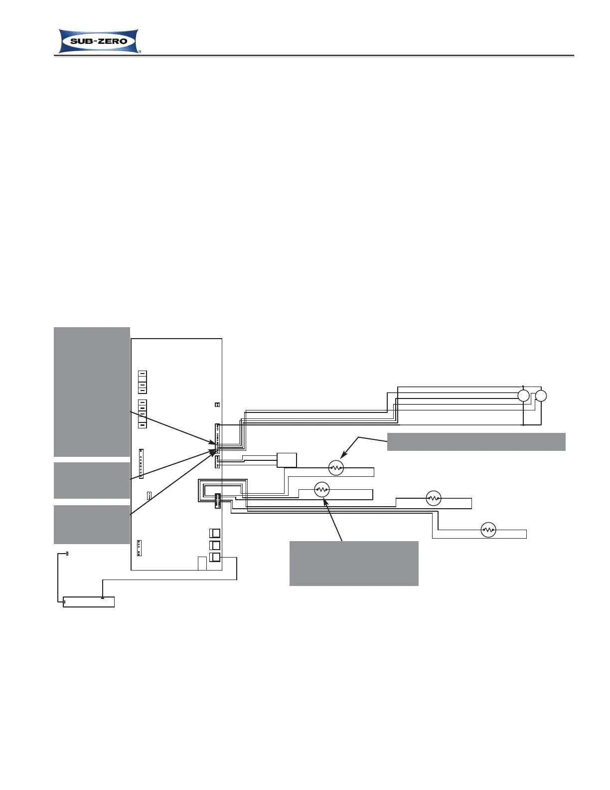
Details of Controlling the Freezer Variable Speed Evaporator Fan Motor
During normal operation and when the door is closed, the variable speed evaporator fan motor in the freezer zone is
supplied with 12V DC at all times from P2-14 off of the control board, with the ground or neutral return to P2-1, and
to ensure proper speed commands the fan’s RPM is monitored at all times via P2-15. The fan will receive a high-
speed run command from P2-12, and stay running at high-speed whenever the freezer compressor is energized,
unless the call for cooling follows a defrost, in which case the evaporator fan will not be switched ON until the freez-
er evaporator is 35°F (2°C) or colder. If the freezer door is opened while the evaporator fan is operating, the micro-
processor will detect the power signal to the lights and interrupt the 12V DC power to the fan. And, if the maximum
ice production feature is activated, which forces the freezer evaporator fan ON 100% for twenty-four (24) hours, the
fan speed will then be ramped down to low-speed during the compressor off cycles. (See Figure 3-45)
NOTE:
• During Sabbath Mode the lighting system is disabled and the 12V DC supplied to the evaporator fan cannot be
interrupted, so the evaporator fan may be observed running when the door is open.
• If improper RPM signals are detected from the evaporator fan, the appropriate fault code will be logged.
1. 12VDC sup-
plied to
motor (P2-14)
4. High-speed
command
sent to motor
(P2-12),
switching to
low-speed
command
only when in
Max Ice Mode
and compres-
sor is in off-
cycle
Motor RPM
monitored at
all time (P2-15)
Figure 3-45. Signal Trace Schematic: Low DC Voltage Variable Speed Freezer Fan Operation
3. Freezer evaporator below 35°F (2°C)
2. Freezer’s high offset tem-
perature detected, switch-
ing compressor & con-
denser fan ON
 Loading...