EasyManua.ls Logo

Sub-Zero SZ-7552-P - User Manual

Sub-Zero SZ-7552-P
5 pages
Print Icon
To Next Page IconTo Next Page
Loading...
Amongst others features, an important one is that
Incase one compressor is not capable of handling the
load, the second compressor will activate and both
compressors will cutout at the lowest set point.
SZ-7552 is two compressor controller with separate
setpoints, differentials and time delays for each
compressor.
The controller features cycling of compressors so that
there is no overload on one compressor.
They are specifically designed for air conditioning
applications wherein the compressor cuts off at setpoint
and is restarted at a temperature of setpoint plus
differential.
Instruction for SZ-7552-P
General Description
1
2
INDEX
4
Parameter
Setting
Press and hold
PRG(prg) key
for 2 seconds.
prg
Display will show ‘P2’ and flash.
To go to other parameters. Use
UP / DOWN keys.
3
Set Point
Function : To set the cutout point
of the controller.
Press & hold
SET key for 2
Seconds.
R1 will flash along with respective
setpoint1 for compressor 1.
The setpoint1 value can now be
changed by using the UP/DOWN
keys. After achieving the desired
value, press the set key and
you will see “- - -” which confirms
that the set point has been stored
in memory.
R2 will flash along with
respective set point 2 for
compressor 2. In the similar
manner use UP/DOWN key to
set the desired value and press
set key to confirm the settings.
Display will change to set point 1
and flash
Set Point 1 & 2
Min Max Fac
O
1.0 C
Set Point 1 & 2
Min Max Fac
O
1 C
O
P2-1 C
rS = 0
rS = 1
rS = Resolution
Set Parameter
P3
O
+1.0 C
P2
O
-1.0 C
O
P3+1 C
SZ-7552-P
www.pvrcontrols.com
INDIA
OPERATING
INSTRUCTIONS
DescriptionParameter Page
Set Point1 and set point 2.
To Set other parameters.
Controller for heating or cooling.
Max. High Temp Limit.
Min. Low Temp. Limit.
Differential.
Probe Calibration.
Time Delay.
To Start 2nd Comp. incase 1st Comp.
Min. Off time between two Comp.
Avoid over loading of Comp.
Keypad Lock.
Relay status on Probe Failure.
To set controller Resolution.
Factory set parameter.
End Programming.
Operating messages.
Technical data.
Suggested Wiring diagram.
Panel cutout & Dimensions.
P1
P2
P3
P4
P5
P6
t2
t3
t4
LP
E1
rS
FS
EP
3
4
5
6
7
8
9
10
11
12
13
14
15
16
17
18
19
20
21
22-23
Question and Answer IconNeed help?

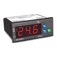
Do you have a question about the Sub-Zero SZ-7552-P and is the answer not in the manual?

Summary

SZ-7552-P Controller General Description

General Description

Introduces the SZ-7552-P as a dual-compressor controller with separate setpoints, differentials, and time delays.

Setting the Cutout Point

Set Point Configuration

Details how to set the cutout point for compressor 1 and compressor 2 using the SET key and UP/DOWN keys.

Controller Parameter Configuration

P1 Parameter: Heating or Cooling Mode

Sets the controller for heating (1) or cooling (0) mode. T2 parameter is active only in cooling mode.

P2 Parameter: Maximum High Temperature Limit

Sets the maximum allowable high temperature limit, preventing set points from exceeding this value.

P3 Parameter: Minimum Low Temperature Limit

Sets the minimum allowable low temperature limit, preventing set points from dropping below this value.

P4 Parameter: Differential Settings

Configures the differential for set point 1 and set point 2 for compressor cycling.

P5 Parameter: Probe Calibration

Allows calibration of the temperature probe to compensate for potential offsets.

P6 Parameter: Time Delay Between Relays

Sets the time delay between the restart of compressor 1 and compressor 2 to prevent simultaneous startups.

t2 Parameter: Second Compressor Activation Delay

To start the second compressor if the first cannot achieve the set point within a specified time.

t3 Parameter: Minimum Off Time Between Compressors

Sets the minimum off-time delay between switching off both compressors to avoid simultaneous shutdowns.

t4 Parameter: Compressor Load Balancing

Avoids overloading of either compressor by interchanging their roles based on time.

E1 Parameter: Relay Status on Probe Failure

Defines the relay behavior when a probe failure is detected.

LP Parameter: Keypad Lock

Locks the keypad to prevent tampering, allowing only viewing of parameters.

rS Parameter: Controller Resolution

Sets the controller's temperature resolution to either 0.1°C or 1°C.

FS Parameter: Restore Factory Defaults

Restores all parameters to their programmed factory default values.

EP Parameter: End Programming

Exits the programming mode and returns the controller to normal operation.

Operating Information and Technical Data

Operating Messages and Icon Status

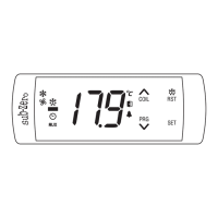
Explains various display messages (Ht, Lt, PP) and icon statuses (R1, R2, LP).

Technical Data

Provides specifications such as housing, dimensions, power input, operating temperature, and accuracy.

Installation and Safety Guidelines

Suggested Wiring Diagram

Illustrates the wiring connections for the controller, compressors, and NTC probe.

Panel Cutout and Installation

Details panel cutout dimensions, mounting, and installation procedures for IP65 rating.

Controller Placement and Probe Installation

Guidelines for installing the controller and probe in suitable environments to ensure accurate readings.

Wiring and Maintenance Cautions

Provides crucial cautions for wiring, warnings against improper handling, and maintenance instructions.

Overview

The SZ-7552-P is a two-compressor controller designed specifically for air conditioning applications. Its primary function is to manage compressor operation, ensuring efficient cooling by cutting off at a setpoint and restarting at a temperature of setpoint plus differential. A key feature of this controller is its ability to cycle compressors, preventing overload on any single unit. Furthermore, if one compressor is unable to handle the load, the second compressor will activate, with both units cutting out at the lowest setpoint.

The controller offers extensive programmability through various parameters, accessible by pressing and holding the SET key for two seconds to enter the setpoint mode, or the PRG key for two seconds to enter the parameter setting mode.

Function Description:

  • Set Point 1 & 2: This function allows users to define the cutout points for each compressor. When in this mode, the display will flash "set point 1," and "R1" will flash along with the respective setpoint for compressor 1. Users can adjust this value using the UP/DOWN keys and confirm by pressing the SET key. The display will show "---" to indicate that the setpoint has been stored. The same process applies to setpoint 2, with "R2" flashing.
  • P1 Parameter (Heating or Cooling): This parameter determines whether the controller operates in heating or cooling mode. A value of "0" signifies cooling mode, while "1" indicates heating mode. The t2 parameter (second compressor start) is only active when P1 is set to "0" (cooling).
  • P2 Parameter (Max. High Temp Limit): This sets the maximum allowable high-temperature limit. Once set, neither setpoint can exceed this value. If the temperature reaches this limit, the display will show "Ht" (High Temperature).
  • P3 Parameter (Min. Low Temp. Limit): This sets the minimum allowable low-temperature limit. Similar to P2, neither setpoint can fall below this value. If the temperature reaches this limit, the display will show "Lt" (Low Temperature).
  • P4 Parameter (Differential 1 & 2): This function sets the differential for both setpoint 1 and setpoint 2. When in this mode, "R1" and the differential for setpoint 1 will flash. Users can adjust the value using UP/DOWN keys and confirm with the SET key. The same applies to setpoint 2, with "R2" flashing. For example, if setpoint 1 is 10.0°C and its differential is 2.0°C, compressor 1 will cut out at 10.0°C and restart at 12.0°C.
  • P5 Parameter (Probe Calibration): This allows for probe calibration to compensate for any offset in temperature readings. Users can adjust the value using UP/DOWN keys to add or subtract degrees, ensuring accurate temperature display. The setting range is from -10.0°C to +10.0°C.
  • P6 Parameter (Time Delay between Relay Restart): This sets the time delay between the restart of compressor 1 and compressor 2. "R1" and the time delay for setpoint 1 will flash, allowing adjustment with UP/DOWN keys and confirmation with the SET key. The same process applies to setpoint 2, with "R2" flashing. An internal 10-second delay is built-in to prevent both compressors from switching on simultaneously, mitigating electrical surges.
  • t2 Parameter (Start Second Compressor): This function activates the second compressor if the first compressor cannot achieve the lower setpoint. If set to a specific time (e.g., 7 minutes), and compressor 1 fails to reach its setpoint within that time, the second compressor will engage. Both compressors will then cut out at the lower setpoint. If t2 is set to 0, this feature is deactivated. This parameter is only active when P1 is set to "0" (cooling).
  • t3 Parameter (Minimum Off Time between Compressors): This sets the minimum off-time between the two compressors, preventing them from switching off simultaneously. If set to 3 seconds, the second compressor will switch off at least 3 seconds after the first. If set to 0, this feature is deactivated.
  • t4 Parameter (Avoid Overloading of Compressor): This function prevents either compressor from being overworked for extended periods. If set to, for example, 2 hours, the setpoint, differential, and time delay of both compressors will interchange every 2 hours. This helps prolong compressor life. The time calculation starts at power-on or after the last change in these parameters.
  • LP Parameter (Keypad Lock): This feature allows users to lock the keypad, preventing unauthorized tampering. "0" means unlocked, and "1" means locked. When locked, all parameters can only be viewed, not modified.
  • E1 Parameter (Relay Status on Probe Failure): This parameter defines the controller's behavior in case of a probe failure.
    • "0": Both relays will stay on with an initial start-up delay of 2 minutes.
    • "1": Both compressors will perform a duty cycle of 10 minutes ON and 4 minutes OFF.
    • "2": Both relays will stay OFF.
  • rS Parameter (Controller Resolution): This sets the display resolution. "0" sets the resolution to 0.1°C, while "1" sets it to 1°C.
  • FS Parameter (Restore Default Settings): Setting this parameter to "1" will program all parameters to their factory default values. This is useful for debugging setting-related problems.
  • EP Parameter (End Programming): Pressing the SET key in this mode will end the programming sequence, and the controller will return to normal operation, displaying the temperature and recording all settings.

Usage Features:

  • Intuitive Interface: The controller uses a combination of SET and PRG keys, along with UP/DOWN keys, for easy navigation and parameter adjustment.
  • Clear Display: The 3x14.2mm (0.56") LED display provides clear readings and flashes to indicate active parameters or messages.
  • Operating Messages: The display provides various messages to inform the user about the controller's status:
    • "Ht": Temperature equal to or above the maximum limit.
    • "Lt": Temperature equal to or below the minimum limit.
    • "PP": Probe short circuit, open circuit, or without probe; or temperature outside the defined range (e.g., >50.0°C or <0.0°C for rS=0).
    • "R1 ON/OFF": Compressor 1 relay ON/OFF.
    • "R2 ON/OFF": Compressor 2 relay ON/OFF.
    • "On/Off": Keypad locked/unlocked.
    • "R1 Flashing": Time delay in progress for Compressor 1.
    • "R2 Flashing": Time delay in progress for Compressor 2.
  • Keypad Lock: The LP parameter allows users to lock the keypad, preventing accidental or unauthorized changes to settings.
  • Resolution Control: The rS parameter enables users to select the desired temperature display resolution (0.1°C or 1°C).
  • Factory Reset: The FS parameter provides a convenient way to restore all settings to their factory defaults, which can be helpful for troubleshooting.

Maintenance Features:

  • Probe Calibration (P5): Allows for precise adjustment of temperature readings to compensate for any probe inaccuracies over time.
  • Avoid Overloading (t4): The automatic interchange of setpoints, differentials, and time delays helps distribute workload evenly between compressors, extending their lifespan.
  • Probe Failure Management (E1): The controller offers configurable responses to probe failures, ensuring continued operation or safe shutdown depending on the chosen setting.
  • Cleaning: The surface of the controller should be cleaned with a soft, moist cloth. Abrasive detergents, petrol, alcohol, or solvents should not be used.
  • Wiring Precautions: The probe and its wires should not be installed in a conduit next to control or power supply lines. Electrical wiring should follow the provided diagram, and the power supply circuit should be connected to a protection switch. Terminals accommodate wires up to 2.5 sq mm. Improper wiring can cause damage and personal injury, so it must be done by qualified personnel.

Sub-Zero SZ-7552-P Specifications

General IconGeneral
TypeTemperature Controller
Temperature Range-58 to 302°F (-50 to 150°C)
DisplayLED
Width72 mm
Resolution0.1°F
Input TypeThermocouple (Type K)
Output TypeRelay (SPDT)
Height2.83 inches (72 mm)

Related product manuals