EasyManua.ls Logo

Sub-Zero SZ-7510-P-DI User Manual

Sub-Zero SZ-7510-P-DI
5 pages
To Next Page IconTo Next Page
Page #1 background imageLoading...
Page #1 background image
OPERATING
INSTRUCTIONS
SZ-7510-P-DI
www.subzero.co
1
4
GENERAL DESCRIPTION
The Sub-Zero Series SZ-7510-P-DI are aesthetically superior
versions of their predecessors. The SZ-7510-P-DI is a single
set point controller. with digital input. They are specifically
designed for refrigeration applications wherein the
compressor cuts off at set point and is restarted at a
temperature of set point plus differential.
Additionally these controllers offer several protection features
that are easily understood by the examples in the instructions
below. The controller can be used for heating applications,
when the P1 parameter is set to “1” .
A number of parameters are displayed alphanumerically to set
up the instrument for each specific application.
The SZ-7510-P-DI controller can be used for several
O O
applications with a measuring range from -50 C to 99 C.
Instructions :
Function: To set the cut out
point of the controller.
Display will change to set range.
The set point range can now be
changed by using the UP/DOWN
key. After setting the desired
range, press the set key and you
will see “- - -” which confirms that
the set point has been stored in
memory.
Set point
Press and hold
the SET
key for
2 Seconds.
O
-50
C
O
99
C
O
10 C
Min
Max
Fac.
3
INDEX
Para. Page
Description
P1
P2
P3
P4
P5
P6
d0
d1
d2
d3
LP
E1
FS
EP
3
4
5
6
7
8
9
10
11
12
13
14
15
16
17
18
19
20
21
22
2
INDIA
To set other
Parameters.
Display will show P1 & flash.
To go to other parameters,
use UP/DOWN keys.
Press & hold
the DOWN(prg)
key for
2 seconds.
prg
SET
To set the SET Point of the controller.
How to set other parameters.
To set Heating or Cooling function.
Max High Temp limit & alarm.
Min Low Temp limit & alarm.
To set Differential (Hysterisis).
Probe calibration.
Time Delay (relay restart after cutoff)
Keypad lock.
Relay status on probe failure.
Restore factory defaults.
End Programming.
Operating messages.
Technical Data.
Wiring diagram.
Panel cutout & dimensions.
Activate or deactive digital input function.
Set reset mode for digital input
Set the count mode for CCF
Set the number of count for CCF
Question and Answer IconNeed help?

Do you have a question about the Sub-Zero SZ-7510-P-DI and is the answer not in the manual?

Sub-Zero SZ-7510-P-DI Specifications

General IconGeneral
BrandSub-Zero
ModelSZ-7510-P-DI
CategoryTemperature Controller
LanguageEnglish

Summary

General Description and Operation

General Description

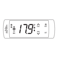
Overview of the Sub-Zero Series SZ-7510-P-DI controller's features and applications.

Setting the Set Point

Step-by-step guide on how to set the cut-out point of the controller.

Accessing Other Parameters

Instructions on how to access and navigate through various controller parameters using keys.

Parameter Configuration (P1-P6)

P1 Parameter: Heating or Cooling Function

Configuration of the controller for either heating or cooling mode.

P2 Parameter: Maximum High Temperature Limit

Setting the upper limit for temperature and associated alarm.

P3 Parameter: Minimum Low Temperature Limit

Setting the lower limit for temperature and associated alarm.

P4 Parameter: Differential Setting

Configuration of the differential (hysteresis) for relay cut-in/cut-out.

P5 Parameter: Probe Calibration

Adjusting the probe reading to compensate for calibration errors.

P6 Parameter: Compressor Restart Time Delay

Setting a delay to prevent compressor restart within a short period.

Advanced Parameter Settings (d0-d3, LP, E1)

d0 Parameter: Digital Input Function

Activating or deactivating the digital input function.

d1 Parameter: Digital Input Reset Mode

Setting the reset mode for the digital input.

d2 Parameter: Compressor Count Fault Mode

Configuring the count mode for Compressor Count Fault (CCF).

d3 Parameter: Compressor Reset Cycles Limit

Setting the permissible number of compressor reset cycles within 1 hour.

LP Parameter: Keypad Lock Function

Enabling or disabling the keypad lock to prevent tampering.

E1 Parameter: Relay Status on Probe Failure

Defining the relay behavior when a probe failure occurs.

Parameter Functions (FS, EP) and Status

FS Parameter: Restore Default Settings

Restoring all controller parameters to factory default values.

EP Parameter: End Programming

Exiting programming mode and returning to normal operation.

Operating Messages and Icon Status

Explanation of on-screen messages and status icons.

Technical Data and Installation

Technical Data

Specifications including housing, dimensions, power, and operating ranges.

Wiring Diagram

Schematic illustration of the controller's electrical connections.

Panel Cutout and Dimensions

Details on the physical dimensions and panel mounting requirements.

Installation, Safety, and Notices

Installation Instructions

Guidance on fixing the unit, panel mounting, and sealing for IP65.

Controller and Probe Installation Environment

Recommendations for installing the controller and probe to ensure correct operation.

Cautionary Notes on Wiring and Maintenance

Important warnings and advice regarding electrical wiring and cleaning.

Document and Warranty Information

Information on document usage rights, liability, and product warranty.

Related product manuals