Do you have a question about the Sub-Zero SZ-CRC-1100A and is the answer not in the manual?
To set the cut-out point of the controller.
To set the maximum allowable high temperature limit.
To set the minimum allowable low temperature limit.
To set compressor differential (hysteresis).
To set room probe offset calibration.
To set time delay between compressor relay restart time.
To set compressor relay status on room probe failure.
To set door open alarm delay.
Evaporator fan stop coil temperature.
Time delay between evaporator fan relay restart.
Evaporator fan operation when compressor is off.
Evaporator fan differential (hysteresis).
To set coil probe offset calibration.
Evaporator fan status during defrost.
Evaporator fan status on door open.
Cyclic ON time of compressor relay.
Cyclic OFF time of compressor relay.
To set condenser delay to start before compressor.
Condenser relay status during Hot gas defrost.
To set quick freeze set point.
To set Quick Freeze time duration.
To set/activate power up defrost cycle.
To set type of defrost.
To set type of computation for defrost frequency.
To set defrost frequency.
To set maximum defrost duration.
Defrost stop temperature (Evap. coil probe).
Alarm to check heater function.
To set display during defrost.
To set maximum defrost duration on coil probe fail.
Power on time delay for Alarm (HT/LT).
To lock keypad.
Revert to factory set parameters.
To end programming.
To give a correct reading, the probe must be installed in a place protected from thermal influences.
The probe and its corresponding wires should never be installed in a conduit next to control or power supply lines.
Improper wiring may cause irreparable damage and personal injury.
Clean the surface of the controller with a soft moist cloth.
Information in this document is subject to change without prior notice.
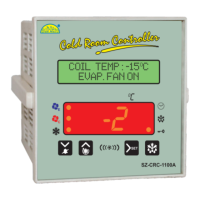
The Subzero Cold Room Controller CRC-1100A is a sophisticated temperature control device designed for refrigeration applications, ensuring precise management of cold room environments. It operates on a positive differential principle, where the compressor stops upon reaching the setpoint temperature and restarts when the temperature rises to the setpoint plus the differential. This mechanism helps maintain stable temperatures within the cold room.
The controller offers two distinct defrost types: electrical defrost, which involves stopping the compressor and activating a heater, and hot gas defrost, where the compressor continues to operate while a heater is active. Additionally, a time-based defrost option is available, which functions independently of the evaporator coil probe temperature and relies solely on a set time duration. The device allows users to configure the interval between defrost cycles and a maximum time-out after which defrost is interrupted, providing flexibility in managing defrost operations. The same probe used for defrost control also manages the evaporator fans, and users can set the fan stop temperature, a delay time after defrost, and the relationship between the fans and the compressor.
A series of "safety controls" are integrated into the CRC-1100A to protect the compressors from frequent starts. These include a delay at start-up, a minimum disable time, and a minimum time between activations. In the event of a probe error or a temperature alarm, the controller signals the issue through an acoustic alarm and by closing a relay contact. The buzzer can be silenced and the relay contact opened by pressing the mute key. The controller's functions are highly customizable through various programming parameters, allowing it to be adapted to diverse applications.
The device features an LCD with backlighting and a 7-segment display for clear visibility of all parameters. It uses two NTC probes for monitoring cold room temperature and evaporator coil temperature, covering a range from -50°C to +50°C with 1°C resolution. The relay outputs include controls for the compressor, heater, evaporator fan, condenser fan, and an alarm. An audible alarm provides immediate notification of critical events. Digital inputs are available for a door switch and a pressure cutout, enhancing safety and operational control. The controller also incorporates HP/LP/OSS trip protection for the compressor, a compressor protection algorithm, and both automatic and manual defrosting facilities based on time and temperature. A special software feature is included to indicate probable heater faults.
Key operations include setting the cut-out point of the controller, which is the setpoint. This value can be adjusted using the UP/DOWN keys, and the change is confirmed by a visual indicator. Other parameters, such as the maximum allowable high temperature limit (P2) and the minimum allowable low temperature limit (P3), can also be set. The controller prevents the setpoint from exceeding these limits. For instance, if P2 is set to -25°C, the setpoint cannot be adjusted above this value. If the temperature reaches or exceeds P2, a high temperature alarm (Ht) is triggered, activating the alarm relay and buzzer. Similarly, if the temperature falls below P3, a low temperature alarm (Lt) is activated.
The room probe differential (P4) allows users to set the hysteresis, defining the temperature difference between the cut-out and cut-in points for the compressor relay. For example, if the setpoint is 10°C and the differential is 2°C, the compressor will cut out at 10°C and cut in at 12°C. The room probe offset calibration (P5) enables adjustment of the displayed temperature to match the actual temperature, compensating for any sensor inaccuracies over time.
The compressor time delay (P6) protects the compressor from frequent restarts by enforcing a minimum delay between relay restarts, which can be set from 0 to 30 minutes. This is particularly useful in environments with sudden temperature changes, such as near a cold room door. The drip time (P7) sets the duration during which the fan, compressor, condenser, and heater remain off to allow defrost water to drain, adjustable from 0 to 20 minutes. The compressor relay status on room probe failure (P8) can be configured to keep the compressor relay on, off, or to perform a cyclic on/off operation. If set to cyclic, the cyclic ON time (9A) and cyclic OFF time (9B) parameters determine the compressor's operational pattern.
The door alarm delay (P9) sets the delay before an alarm is triggered if the door remains open, ranging from 0 to 30 minutes. The evaporator fan stop coil temperature (L1) defines the temperature at which the evaporator fan will cut off. The fan time delay (L2) sets a delay between evaporator fan relay restarts, preventing rapid cycling. The fan operation when the compressor is off (L3) can be configured to either turn the fan off or keep it on.
The coil probe differential (L4) sets the hysteresis for the evaporator fan, similar to the room probe differential. The coil probe offset calibration (L5) allows for adjustment of the evaporator fan coil probe's temperature reading. The fan status during defrost (L6) can be set to either keep the fan off or on during defrost. The fan status on door open (L7) determines whether the fan stays on or turns off when the door is open.
The condenser start delay (d1) sets a delay for the condenser to start before the compressor, while the condenser relay status during hot gas defrost (d2) can be configured to keep the condenser off or on. The quick freeze set point (CS) allows users to define a specific temperature for quick freeze mode, and the quick freeze duration (Ct) sets the time for which this mode operates.
The power-on defrost (E0) parameter enables or disables a power-up defrost cycle, which can be set to occur after a specified time (e.g., 1, 2, or 3 hours). The type of defrost (E1) can be selected as heater defrost, hot gas defrost, or time-based defrost. The defrost time calculation (E2) determines whether defrost frequency is based on total real time or the sum of total compressor operating times. The defrost frequency (E3) sets the interval between defrost cycles. The maximum defrost duration (E4) defines the longest time allowed for a defrost cycle. The defrost stop temperature (E5) sets the evaporator coil temperature at which the defrost process will terminate.
The heater check function (E6) provides an alarm if the coil temperature does not rise sufficiently during a heater defrost, indicating a potential heater fault. The display during defrost (E7) can be set to show either the room temperature or "dF" (defrost). The maximum defrost duration on coil probe failure (E8) sets a time limit for defrost if the coil probe fails. The power-on alarm delay (AL) prevents nuisance alarms by delaying alarm activation after power-on. The keypad lock (LP) parameter allows users to lock the keypad to prevent unauthorized tampering. Finally, the reset parameters (FS) function reverts all settings to factory defaults, which is useful for debugging.
Maintenance of the controller involves cleaning its surface with a soft, moist cloth, avoiding abrasive detergents, petrol, alcohol, or solvents. The device is designed for easy installation, with mounting clamps and screw terminals for wiring. The wiring diagram provides clear instructions for connecting the probes, digital inputs, and relay outputs. The controller should be installed in a location protected from vibration, water, and corrosive gases, where the ambient temperature remains within the specified technical data. Probes must be installed in a location protected from thermal influences to ensure accurate readings. Proper wiring, performed by qualified personnel, is crucial to prevent damage and ensure safety.
| Model | SZ-CRC-1100A |
|---|---|
| Brand | Sub-Zero |
| Compatibility | Sub-Zero Refrigeration Units |
| Frequency | 60 Hz |
| Features | alarm notifications |
| Operating Temperature | 32°F to 100°F (0°C to 38°C) |
| Humidity Range | 10% to 90% non-condensing |