Do you have a question about the Sub-Zero Mega Chill and is the answer not in the manual?
Controller manages refrigeration units with different configurations, supporting water and air condensation.
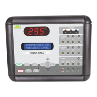
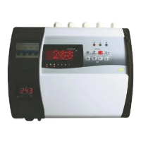
Overview of the basic system components: Mega Chill User Interface, Input/Output board, and intelligent Mega Chill unit.
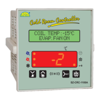
User-friendly board integrating controller keys, LCD display, and LED indicators for status.
The core system board where signals from probes and digital inputs are processed.
Japanese NTC thermistors housed in waterproof IP68 metal casing for temperature sensing.
Hardware key enabling manufacturer access to Level 2 (Factory Level Programming).
A highly reliable toroidal transformer serves as the system's power supply source.
Technical drawings showing the dimensions of the Input/Output Board and Mega Chill User Interface.
Details on wiring the Chiller Interface Terminal and the Input/Output Board with diagrams.
Detailed explanation of analog inputs (probes) and digital outputs (relays) used by the system.
Overview and function of the buttons on the Mega Chill controller's keypad for operation.
Step-by-step guide for starting and stopping the chiller controller, including auto-start notes.
Details on the water pump's operation, priority, status, and blocking alarms.
Explanation of how water temperature regulation is managed by the CONTROL PROBE.
Defines set point for chiller regulation and differential for compressor restart.
Describes the antifreeze procedure, its activation threshold, and how to disable it.
Explains the PUMP-DOWN procedure and cycle for refrigerant migration during OFF cycles.
How the system controls water level using three sensors and activates a solenoid valve.
Details the two levels of programming: User and Manufacturer (via Prokey).
Instructions for accessing and modifying user-level parameters using the keypad.
Explains factory parameters protected by a Prokey, requiring hardware key insertion for access.
Detailed table and explanation of various parameters, their settings, and units.
Specifications for sensor type, resolution, accuracy, and temperature range.
Details on maximum continuous voltage and input current for digital inputs.
Specifications for relay type, contacts, rating, and fusing of digital outputs.
Operating temperature range for the User Interface and Relay Board.
Storage temperature range for the User Interface and Relay Board.
Maximum operating humidity for the device.
Maximum storage humidity for the device.
Information on panel mounting for the User Interface and Relay Board.
IP ratings for the probe, user interface, and I/O board.
Minimum cable section size for the screw terminal relay board.
Maximum cable section size for the screw terminal relay board.
Specification for the fuse used in the system.
Specifications for the toroidal transformer's primary and secondary inputs/outputs.
Guidelines for cleaning the controller surface using a soft cloth and avoiding abrasive detergents.
Caution regarding improper wiring causing irreparable damage and injury; use qualified personnel.
| operating temperature | -50 C to +50 C0 |
|---|---|
| storage temperature | -20 C to + 70 C |
| operating humidity | Max 80% (non-condensing) |
| storage humidity | Max 80% (non-condensing) |
| max continuous input voltage | 230 Vac |
|---|---|
| input current (closed contact) | 10 mA |
| transformer primary input | 230Vac, 50Hz |
| transformer secondary output 1 | 9Vac, 350mA |
| transformer secondary output 2 | 10Vac, 500mA |
| type | SPDT |
|---|---|
| contacts | C & NO (C, No, NC for compressor) |
| rating | 250 Vac, 5A(resi) |
| sensor type | Japanese NTC thermistors |
|---|---|
| specification | 10K @ 25 C0 |
| resolution | 0.5 C0 |
| accuracy | +/- 1 C0 |