12
13
4.1 Description- Input /Outputs
Analog Inputs (Probe)
The system has the following
analog (probe) inputs.
1. CONTROL - Used as the
main controlling probe based
on which the set point will
regulate the system.
2. COND IN - Indicates
Condenser Inlet temperature.
3. COND OUT - Indicates
Condenser Outlet
temperature.
4. WATER IN - Senses Water
(Chiller) Inlet temperature.
5. WATER OUT - Senses Water
(Chiller) Outlet temperature.
6. ANTI FREEZE : Used as an
Internal Anti Freeze control.
Digital Outputs (Relay)
System will operate the following
devices
1. Chiller Pump
2. Compressor1
3. Condenser Fan1
4. Liquid SV1 for Pump Down1
5. Compressor2
6. Condenser Fan2
7. Liquid SV2 for Pump Down2
8. Water SV
9. Alarm
Mega chill manages the following
protections
Digital Inputs (Trip Signals)
1. HP1 - High Pressure for Comp1
2. LP1 - Low Pressure for Comp1
3. Compressor Overload1
4. OSS1 - Oil Safety Switch1
5. COND. Fan O/L1 -
Condenser Fan Overload1
6. HP2 - High Pressure for Comp2
7. LP2 - Low Pressure for Comp2
8. Compressor Overload2
9. OSS2 - Oil Safety Switch for
Comp2
10.COND. Fan O/L2 -
Condenser Fan Overload2
11.EWFS (water cooled)-
Evaporator Water Flow
Switch.
12.Pump Overload
13.Single Phase Preventor
14.Antifreeze Trip (Internal)
15.R - R Phase (Input)
16.Y - Y Phase (Input)
17.B - B Phase (Input)
Controller informs the user of a fault
condition via a Buzzer and an
ALARM RELAY.
WARNING :
All HP, LP, OSS and Antifreeze are by default in manual
reset mode. In case of any fault the user can reset them by
pressing the CLEAR key for 4 sec. These can be changed
to auto reset by changing P4 parameter.
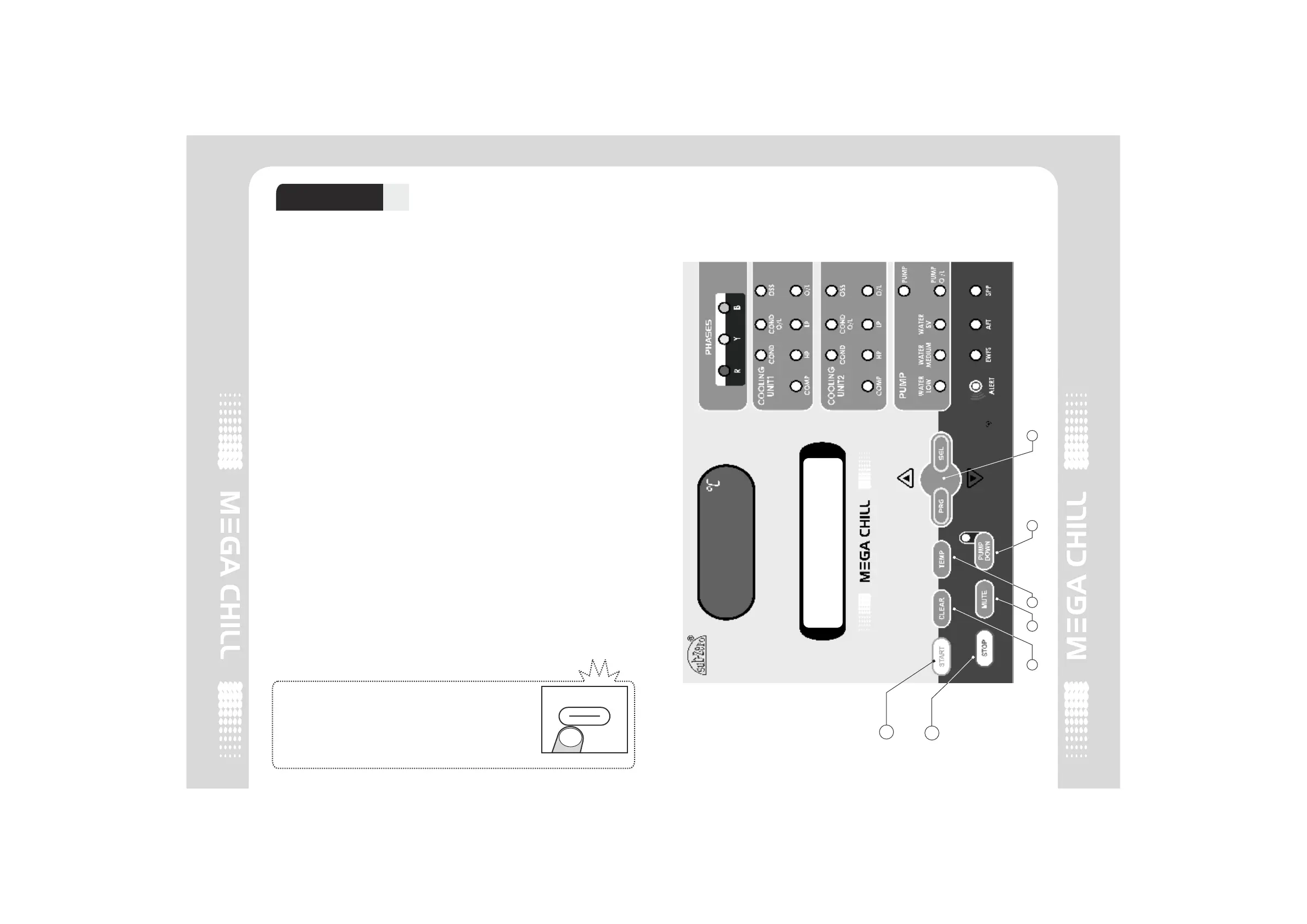
4. Operations
00.04
MUTE
CLEAR
4.2 Mega Chill Keypad
1
2
3 4 5 6 7
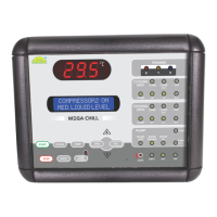
COMPRESSOR2 ON
MED. LIQUID LEVEL
2 COMPRESSOR2 COMPRESSOR
29.5