16
17
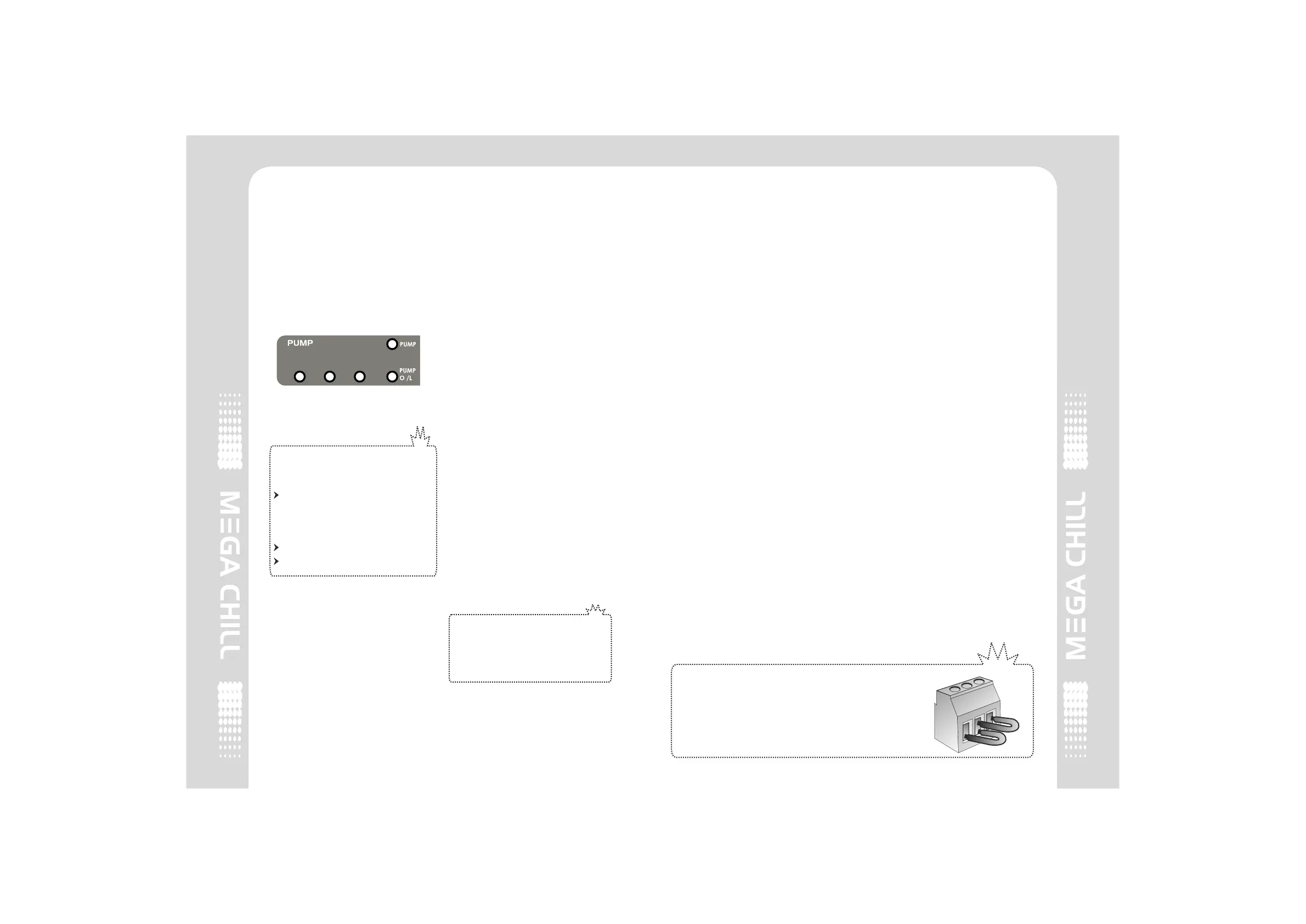
4.4 Water Pump
PUMP is the first device to be
activated after the chiller has
started. Pump functioning has
absolute priority amongst all other
devices.
The pump’s status is always ON
even if the set temperature has
been achieved.
ALARMS
The alarms that can block
the pump are:
WATER FLOW SWITCH
(This alarm is ignored for
a selected time as
per parameter P1 & P2)
PUMP OVERLOAD
LOW LIQUID LEVEL
4.6 Set-Point and Differential
Set point is the temperature at
which the chiller has to be
regulated. At this temperature the
compressor will switch off.
Differential is the temperature
added to the set point after which
the compressor restarts. For
0
example, If the Setpoint is 7 C,
0
and the differential is 2 C, the
0
compressor will switch off at 7 C
0 0 0 0
and restart at 9 C (7 C+2 C=9 C).
4.7 Antifreeze
The antifreeze procedure
activates when the AFT probe
temperature reaches or goes
below the selected threshold in
parameter A1, The compressors
are immediately stopped, without
pump-down procedure and the
liquid line solenoid valve is de-
energised. The antifreeze alarm is
displayed on the LCD.
The system will not allow a restart
until AFT temperature reaches or
goes above A1 + A2.
To disable the ANTIFREEZE
based on the internal AFT
probe, change A0 parameter
to 0.
4.5 Water temperature
Regulation of the water
temperature is based on the
CONTROL PROBE. This control
probe can be installed by the user
at the inlet or outlet of the
evaporator, or any other location,
where he wants to regulate the
water / media.
4.8 PUMP-DOWN
The PUMP-DOWN procedure can
be enabled through H1 parameter.
PUMP-DOWN STAGE :
A. De-energisation of the Liquid
Solenoid Valve.
B. The compressor keeps
operating until the LOW pressure
cutout input intervenes.
C. When the system cuts off on the
input from the low pressure cutout,
the compressor turns OFF and the
PUMP-DOWN procedure is over.
If the compressor remains on for
more than 50 seconds without
cutting off on the low pressure
switch, Megachill will force a
compressor shut down and
indicate a FAULTY PUMP-DOWN
procedure provided the CUT IN
temp has not been achieved. In
this case check the LIQUID
SOLENOID VALVE and LOW
PRESSURE CONTROL. If within
50 seconds, the CUT IN temp has
been achieved, the system will
activate the solenoid and continue
operating normally without pump
down.
PUMP-DOWN CYCLE
A pump-down cycle is used to
pump all refrigerant into a receiver
or condensor during the OFF cycle.
The purpose is to prevent
refrigerant from migrating to the
crankcase, where it can condense
and saturate the oil. Without a
pump-down cycle, the crankcase
can fill liquid refrigerant during a
long off-cycle. At start up, the liquid
refrigerant can flood the cylinders
and damage the compressor much
lik e a f l ood b a ck . ( L arg e
compressors have springs on
intake) After the system has cooled
the evaporator sufficiently, a
solenoid valve closes in the liquid
line and the compressor pumps
refrigerant into the condenser or
receiver, where it remains until the
next on-cycle.
4.9 Water Level
System controls the level of water
in the evaporator tank via three
water level sensors, High, Med &
Low. As soon as the level of water
goes below the Medium level, the
controller will activate a Water
Solenoid Valve. In case the level
goes below the Low level sensor,
the system trips and displays a Low
Liquid Level Fault.
WARNING
If the machine controlled by mega chill is not using
the water level sensing feature, it is necessary to
short all water inputs concerning the water level.
This will disable the liquid level errors.
2 COMPRESSOR2 COMPRESSOR
WATER
MEDIUM
WATER
LOW
WATER
SV