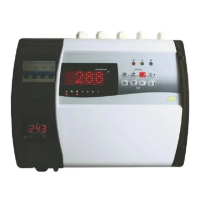
The Sub-Zero CRC-2020 is a single set point cold room controller designed for precise temperature management in cold storage environments. It offers a range of features to ensure optimal performance, safety, and ease of use.
Function Description:
The CRC-2020 controls defrost cycles based on time, with the compressor stopping during defrost. Users can set the interval between defrosts and a maximum time-out for defrost interruption. The controller incorporates several safety features, including system shutdown in case of faults from pressure controls or similar devices. It also includes "safety controls" such as delays at start-up, minimum disable times, and minimum time between activations to protect compressors from frequent starts. In the event of a probe error or temperature alarm, the instrument signals the event acoustically and by closing a relay contact. The buzzer can be silenced by pressing the mute key. The controller can be used in various applications with a measuring range from -50.0°C to 50.0°C. Optional computer connectivity over RS485 allows for remote monitoring.
Important Technical Specifications:
Housing:
- Plastic: (H)400 x (W)300 x (D)135 mm
- Sheet Metal: (H)450 x (W)400 x (D)200 mm
Mounting:
- Wall mounting
- Spring clamp terminal block, 4 sq. mm wire
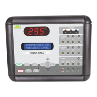
Display:
- 4 Digit, 1" Dot matrix Display
- 8 LEDs for indication
Data Storage:
- Non-Volatile EEPROM Memory
- 415Vac +/-10%, 50-60Hz, 3Phase Supply with Neutral
Operating Temperature:
- 5°C to 50°C (non-condensing)
Storage Temperature:
- -20°C to 70°C (non-condensing)
Output Relays:
- Compressor Relay: 5A/230Vac
- Evap. Relay: 5A/230Vac
- Light Relay: 5A/230Vac
- Alarm Relay: 5A/230Vac
Temperature Sensor:
- Sensor Type: NTC Thermistor
- Resolution: 0.1°C
- Accuracy: +/-1°C
- Probe Tolerance at 25°C: +/-0.3°C
- Range: -50.0°C to 50.0°C
- Resolution: 0.1Amp.
- Accuracy: +/-1 Amp.
- HP, LP, Auxiliary, Door, SPPR, OPS, R-Ph, Y-Ph, B-Ph.
Buzzer:
RS485 Connectivity:
- Modbus RTU Protocol
- Baud Rate: 9600
- Device ID: 1 (By Default)
Usage Features:
Set Point (SP):
- Sets the cut-out point of the controller.
- Adjustable using UP/DOWN keys.
- Range: P3+0.5°C to P2-0.5°C, default 0.0°C.
High Temperature Limit (P2):
- Sets the allowable high temperature limit.
- Prevents the set point from exceeding this value.
- Triggers "Ht" alarm if room temperature reaches or exceeds this limit.
- Range: SP+0.5°C to 50.0°C, default 50.0°C.
Low Temperature Limit (P3):
- Sets the allowable low temperature limit.
- Prevents the set point from falling below this value.
- Triggers "Lt" alarm if room temperature reaches or falls below this limit.
- Range: -50.0°C to SP-0.5°C, default -50.0°C.
Compressor Restart Differential (P4):
- Sets the temperature differential for compressor restart.
- Example: If set point is 10.0°C and differential is 2.0°C, compressor cuts out at 10.0°C and cuts in at 12.0°C.
- Range: 0.5°C to 20.0°C, default 2.0°C.
Probe Calibration (P5):
- Allows for probe calibration to compensate for display offsets.
- Adjustable using UP/DOWN keys to add or subtract degrees.
- Range: -10.0°C to 10.0°C, default 0.0°C.
Relay Restart Time Delay (P6):
- Sets the time delay between relay restarts to protect the fan/compressor.
- Range: 1 Min to 20 Min, default 3 Min.
Defrost Duration (P7):
- Sets the maximum duration allowed for defrost.
- If set to 0, no defrost cycle occurs.
- Range: 0 Min to 99 Min, default 30 Min.
Defrost Frequency (P8):
- Sets the interval between defrost cycles.
- Range: 1 Hr to 31 Hrs, default 6 Hr.
Power-On Defrost Delay (P9):
- Sets the time delay after power-on before defrost occurs.
- Range: 0 Min to 99 Min, default 30 Min.
Buzzer Enable/Disable (BUZ):
- Enables or disables the acoustic buzzer for alarms.
- Options: ENB (Enabled), DIS (Disabled), default ENB.
Alarm Power-On Delay (AL):
- Sets a delay after power-on before alarms activate, preventing nuisance alarms.
- Range: 0 Min to 99 Min, default 30 Min.
Under Load Limit for Compressor Current (C-UL):
- Sets the minimum current limit for the compressor.
- Triggers a "C-UL" fault if current falls below this limit for a specified duration.
- Range: 0.0A to (C-OL - 1.0)A, default 1.0A.
Over Load Limit for Compressor Current (C-OL):
- Sets the maximum current limit for the compressor.
- Triggers a fault if current exceeds this limit for a specified duration.
- Range: (C-UL + 1.0)A to 30.0A, default 10.0A.
Current Sensing Delay (C2):
- Sets the delay for validating current faults.
- Range: 5 Sec to 60 Sec, default 5 Sec.
HP Sensing Enable/Disable (D0):
- Enables or disables High Pressure (HP) sensing.
- Options: ENB (Enabled), DIS (Disabled), default ENB.
LP Sensing Enable/Disable (D1):
- Enables or disables Low Pressure (LP) sensing.
- Options: ENB (Enabled), DIS (Disabled), default ENB.
Fault Sensing Logic (D2):
- Sets the voltage level at which HP/LP/AUX input is sensed as a fault.
- Options: OV (0V), 230V, default OV.
LP Sensing Delay (D3):
- Sets the continuous duration for which LP fault must be present to be sensed.
- Range: 0 Sec to 180 Sec, default 30 Sec.
HP Fault Reset Mode (D4):
- Sets whether HP fault is reset manually or automatically.
- Options: MAN (Manual), AUTO (Automatic), default AUTO.
Compressor Relay Status on Probe Failure (E1):
- Determines compressor relay behavior if a probe fails.
- Options: ON (Relay stays ON), OFF (Relay stays OFF), CYC (Relay performs duty cycle as per TON & TOFF), default CYC.
On Cycle at Room Probe Fail (TON):
- Sets the "ON" duration for the compressor relay during a duty cycle when room probe fails and E1 is set to 'CYC'.
- Range: 1 Min to 30 Min, default 10 Min.
Off Cycle at Room Probe Fail (TOFF):
- Sets the "OFF" duration for the compressor relay during a duty cycle when room probe fails and E1 is set to 'CYC'.
- Range: 1 Min to 30 Min, default 4 Min.
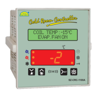
Display at Defrosting (E7):
- Sets what is displayed during defrost.
- Options: TEMP (Temperature), DEFR (Defrost ON scrolling), default TEMP.
Light Switch-Off Time Delay (LD):
- Sets the time delay for automatically switching off the light.
- Range: 0 Min to 30 Min, default 7 Min.
Password (PW):
- Allows changing the password for program mode access.
- Range: 0 to 9999, default 0000.
View Compressor Run Hours (CRH):
- Displays the total compressor run hours (read-only).
Clear Compressor Run Hours (CCRH):
- Resets the compressor run hours.
- Options: NO, YES, default NO.
Unit ID (Unit ID):
- Sets the unique identifier for the device.
- Range: 1 to 240.
Keypad Lock (LP):
- Activates or deactivates keypad lock to prevent unauthorized tampering.
- Options: NO (Deactivates), YES (Activates), default NO.
Power Switch Enable/Disable (PO):
- Enables or disables the power switch function, allowing the controller to be put in active or standby state.
- Options: DIS (Disable), ENB (Enable), default DIS.
Display at Power OFF Mode (PDIS):
- Sets what is displayed when the controller is in power OFF mode.
- Options: LED (Display Blank), TEMP (Temperature), default LED.
Restore Default Settings (FS):
- Restores all parameters to factory default values.
- Options: NO, YES, default NO.
Exit Programming (EP):
- Exits programming mode and returns to normal operation, saving all settings.
Maintenance Features:
- Cleaning: Clean the surface of the controller with a soft, moist cloth. Avoid abrasive detergents, petrol, alcohol, or solvents.
- Probe Installation: The probe must be installed in a location protected from thermal influences to ensure accurate readings.
- Wiring: The probe and its wires should not be installed in a conduit next to control or power supply lines. Electrical wiring should follow the provided diagram, and the power supply circuit must be connected to a protection switch. All wiring should be performed by qualified personnel to prevent damage or injury.