Sr.
No.
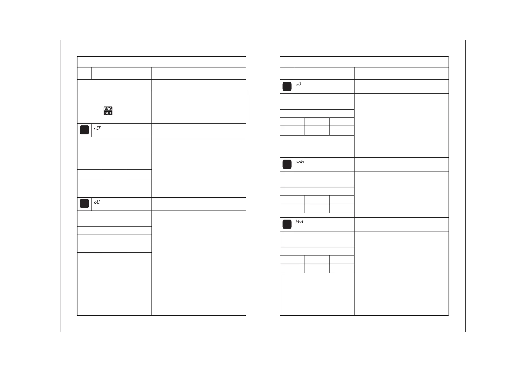
Parameter setting method
Description of parameters and functions.
Parameter
01
Function : To set Reference voltage.
To change the rEF Parameter,
press the set key.
381V 415V 415V
Range
Min Max
Fact. Set
02
Function : To set Overvoltage Limits.
To change the oV parameter,
press the set key.
5V 75V 35V
Range
Min Max
Fact. Set
To set other parameter
Press & hold PRG key for
2 seconds
Display will show ‘rEF’ and scroll the
description of the parameter.
To go to other parameters,
use up / down keys.
Parameter
Parameter
Use UP/DOWN keys to set desired
value.
If the a/c voltages goes above this
limit will trip respective a/c on
Overvoltage(”Ov”) fault.
Example : Over voltage is calculated
depending on Reference voltage + Ov
value. i.e, Ov Set Point = Ref + Ov , When
controller trip on Ov Fault it will recover
when input voltage fall below (Ref - (Ov
/2).
23
Parameter
Parameter
Sr.
No.
Parameter setting method
Description of parameters and functions.
Parameter
03
Function : To set Undervoltage Limits.
To change the uV parameter,
press the set key.
5V 75V
35V
Range
Min Max
Fact. Set
04
Function : To set Un Balance value.
To change the unb parameter,
press the set key.
10V 120V 60V
Range
Min Max
Fact. Set
Use UP/DOWN keys to set desired value.
If the a/c voltages goes below this
limit will trip re spective a/c on
undervoltage(”Uv”) fault.
Example : Under voltage is calculated
depending on Reference voltage - Uv
value. i.e Uv Set Point = Ref - Uv , When
controller trip on Uv Fault it will recover
when input voltage above (Ref – (Uv /2).
Use UP/DOWN keys to set desired
value.
Unbalance fault raised when voltage
difference between any of two phases
goes above Unb value and recovers when
the difference is less than (UNB/2).
Parameter
05
Function : To set time delay.
To change the ttd parameter,
press the set key.
0Sec 60Sec 10Sec
Range
Min Max
Fact. Set
Use UP/DOWN keys to set desired
value.
Time delay provided to avoid false
triggering, when any fault last more than
TTD value then only fault is raised and this
fault is applicable to Under voltage, Over
voltage and Unbalance fault.(i.e., In case
of Phase Loss or Phase sequence fault
alarm will come immediately).
24
VMRC-10/3 VMRC-10/3
Use UP/DOWN keys to set desired value.
Base reference voltage to calculate under
voltage and over voltage values.
Min and Max value will change
according to display type for settings.
Example : If dsP is L-L then Min= 381V,
Max= 415V.
 Loading...