6
7
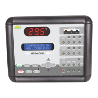
Liquid Crystal Display (LCD)
The LCD screen shows description
of the controller parameters, and
any other information concerning
the controlled variables.
Display 2 rows X 16 characters.
Character Size 5.56 X 2.96 mm.
Liquid Crystal Display (LCD)
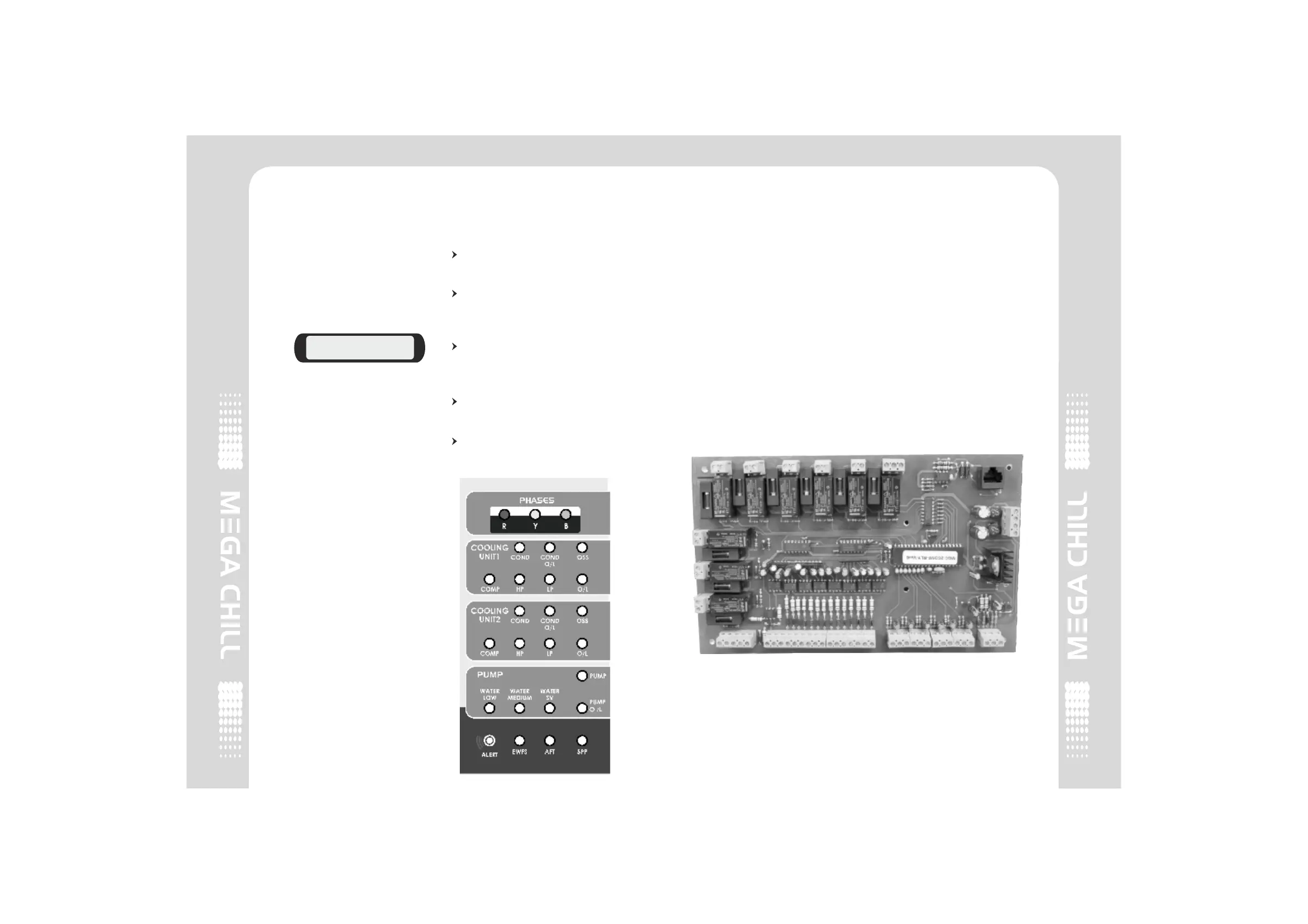
Light Emitting Diodes (LED)
There are 23 LED indications on
the chiller front panel indicating :
Phases - all 3 phases are
displayed as RYB.
Faults - Red blinking LED
ALERT Indicates that there is a
fault.
Individual device fault - Red
LED indicates that there is a
fault in that particular device.
Device OK status - Green LED
indicates that the device is OK.
Device is inactive - Blank LED
indicates that the device is
inactive.
COMPRESSOR 2 ON
MED. LIQUID LEVEL
Light Emitting Diodes (LED)
3.2 Input/Output Board
The Relay board represents the
core of the system, where the
signals coming from the probes,
digital inputs etc. are processed.
On this board you can locate :
1. Terminals for power source-
10Vac (yellow) & 9 Vac (red).
2. Liquid level sensor inputs
(Level Sensors).
3. Analog inputs (sensors).
4. Digital Inputs (alarms).
5. Digital outputs (relay).
6. Telephone connector for user
interface connection.
Input/ Output
2 COMPRESSOR2 COMPRESSOR