5-13
#7012423 - Revision A - August, 2009
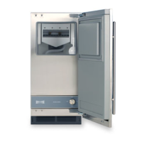
Model UC-15I (Undercounter Ice Machine)
Component Access / Removal
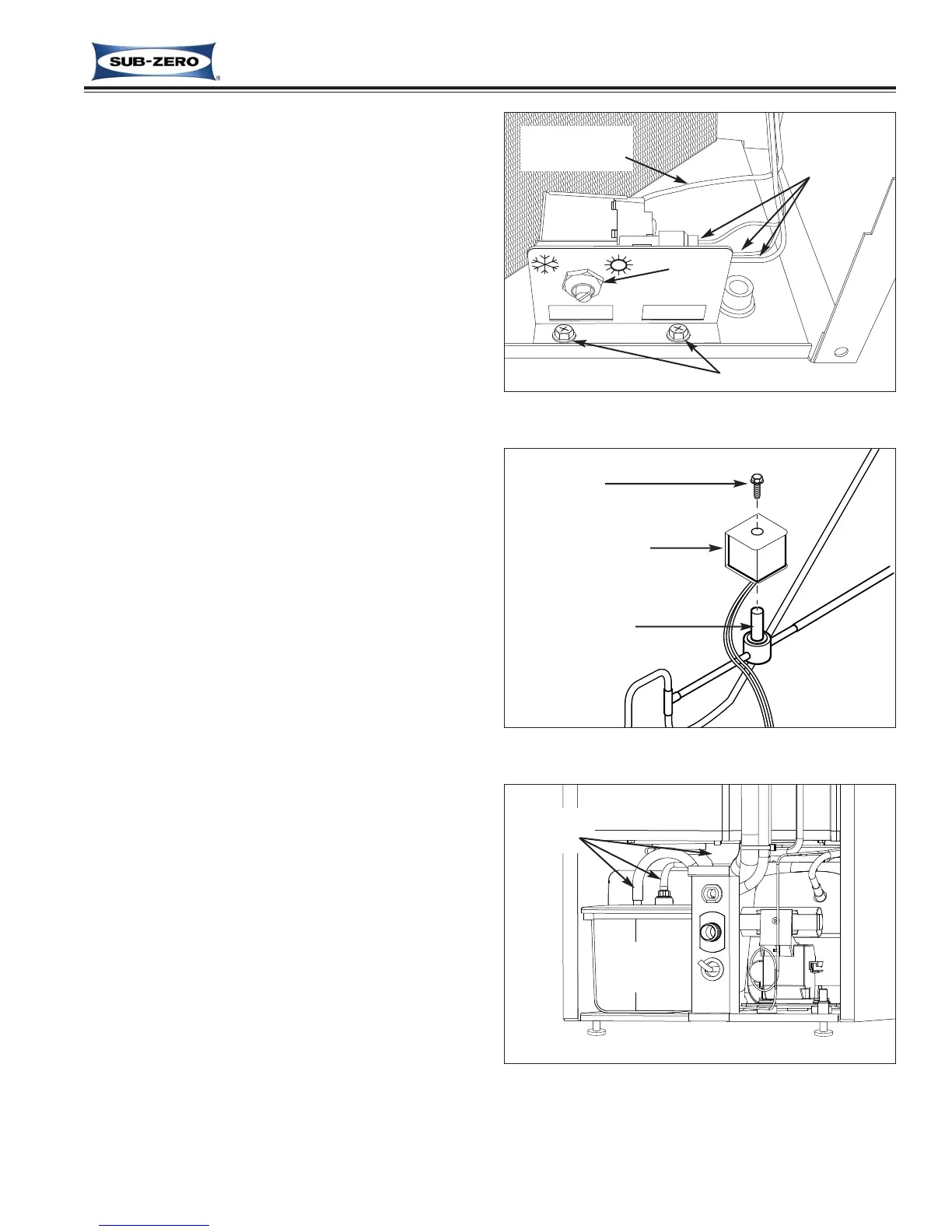
Ice Bin Level (Thermostat) Switch Removal
The ice bin level switch is is located on the lower right
front of the unit behind the kickplate, secured to a
bracket with a nut. The thermostat capillary tube runs
from the rear of the switch to the back of the unit, then
up to a hole in the foam and into the back of the bin
thermostat sensing tube on the left side of the bin.
To remove the ice bin level switch, first remove the kick-
plate and upper back panel, then (See Figure 5-27):
1. Disconnect electrical leads from ice bin level switch.
NOTE: It is recommended to label the wire leads to
assist in proper re-connection.
2. Extract nut that secures ice bin level switch to
bracket.
3. At rear of unit, remove silicone sealant that seals
capillary tube to foam.
4. Inside ice bin, remove silicone sealant at each end
of thermostat sensing tube.
5. Push thermostat sensing tube toward rear of bin
and out through hole in foam, then pull ice bin level
switch from front of unit.
Hot Gas Valve Solenoid Removal
The hot gas valve solenoid is attached to the top of the
hot gas valve body with a screw.
To remove the hot gas valve solenoid, first remove the
upper back panel and lower back utility panel from the
rear of the unit, then (See Figure 5-28):
1. Disconnect solenoid electrical leads.
2. Extract solenoid mounting screw and lift solenoid
from valve body.
Drain Pump Assembly Removal
(UC-15IP & UC-15IPO Only)
The drain pump assembly is located behind the con-
denser at the right rear corner of the compressor area,
adhered to the tray with double-stick tape.
To remove the drain pump assembly, first remove the
upper back panel and lower back utility panel from the
rear of the unit, then (See Figure 5-29):
1. Disconnect inlet, discharge and vent tubes from top
of drain pump.
2. Pry pump assembly up form tray, then pull it toward
rear of unit until electrical leads are exposed.
3. Disconnect electrical leads and pull drain pump
assembly from unit.
Figure 5-27. Ice Bin Level Switch Removal
Nut
Thermostat
Capillary Tube
Bracket Mounting Screws
Electrical
Leads
Switch
Figure 5-29. Drain Pump Removal
Disconnect
Tubing
Drain
Pump
Figure 5-28. Hot Gas Valve Solenoid Removal
Screw
Solenoid Coil
Valve Body