400 Series
400 Series
Component Access and Removal
6-36
After breaking the silicone seal loose, pull the control
panel assembly forward and disconnect the ground wire.
NOTE: When reinstalling the control panel assembly,
you must reapply a bead of silicone along the inside of
the top flange.
MODEL 430 INTERIOR MECHANICAL
COMPONENT REMOVAL:
An attempt has been made to arrange these instruc-
tions in such a way as to simulate which components
would need to be removed first in order to gain access
to other components. When following a component
removal procedure, it may be necessary to reference
another removal procedure towards the front of this
section.
Control Board Access and Removal (Model 430)
The control board is located at the bottom of the com-
partment divider, behind the control panel, and is con-
cealed by an access panel. The control board is held in
place by four tabs, one at each corner of the board.
NOTE: See ELECTRIC SHOCK WARNING and STATIC
ELECTRICITY CAUTION at beginning of this section.
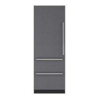
To get to the control board you will need to extract the
two screws at the back of the access panel, then lower
the back of the access panel and pull it towards the rear
of the unit. (See Figure 6-81)
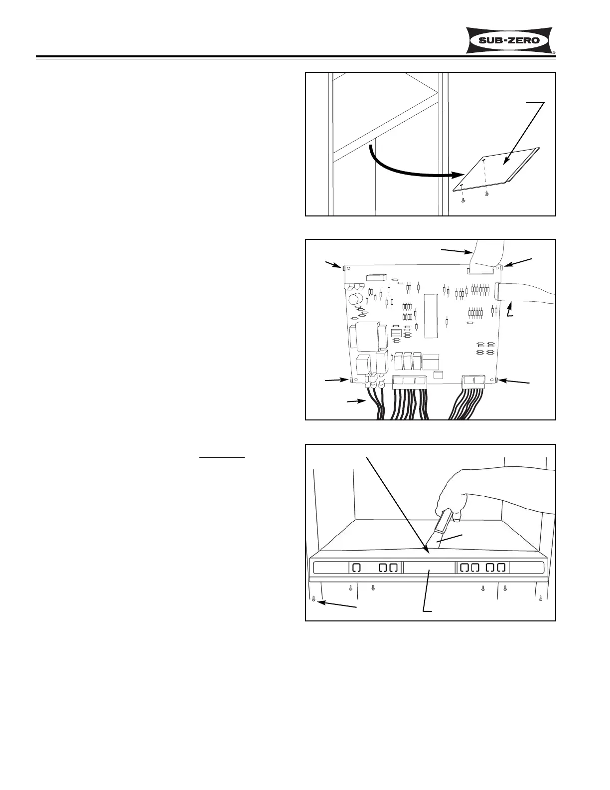
To remove the control board, disconnect the LED ribbon
cable, the membrane switch ribbon cable, and all other
electrical lead attached to the control board. Expand the
tabs to release the control board, then pull down and out.
(See Figure 6-82)
NOTE: When re-connecting electrical leads to the con-
trol board, make sure the silver area on the membrane
switch ribbon cable terminal is facing away from
the con-
trol board.
Control Panel Assembly Removal (Model 430)
The control panel assembly is set at the front of the com-
partment divider and is secured by six screws at the bot-
tom, and a silicone seal under the top flange. Tabs at
the bottom and a concealed tab at the top center of the
control panel housing help to position the control panel
assembly.
NOTE: See ELECTRIC SHOCK WARNING at beginning
of this section.
To remove the control panel assembly, first access the
control board and disconnect the lower light strip wire
leads, LED ribbon cable and the membrane switch ribbon
cable. Then, extract the six screws at the bottom of the
control panel. Now, slide the blade of a putty knife under
and along the top flange of the control panel housing to
break loose the silicone seal. (See Figure 6-83)
NOTE: Do not lift the top flange of the control panel
housing too vigorously. Doing so will break the con-
cealed tab at the top center.
Figure 6-81. Control Board Access Panel
Figure 6-82. Control Board
Figure 6-83.
Control Panel Assembly Removal
Tab
LED Ribbon Cable
Membrane
Switch
Ribbon Cable
Electrical
Connections
Tab
Tab
Tab
Control Panel Assembly
Putty Knife
Screws (6)
Do not break
concealed tab
Access Panel
 Loading...