400 Series
400 Series
Component Access and Removal
6-39
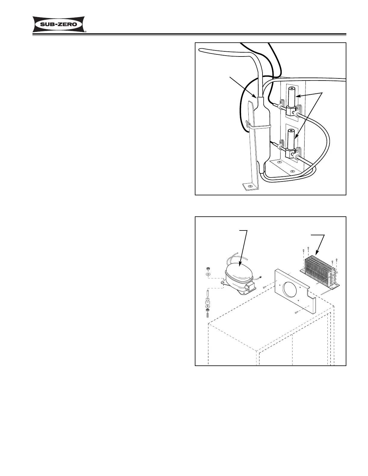
Refrigerant Valve Access and Removal (Model 430)
The refrigerant valves are located to the right of the
compressor, and are held to the valve bracket with P-
clamps and screws. The top valve is for the upper wine
storage compartment and the bottom valve is for the
lower wine storage compartment. (See Figure 6-89)
NOTE: See HOT COMPRESSOR & TUBING CAU-
TION at beginning of this section.
After evacuating the refrigerant from the sealed system,
cut the capillary tube approximately 1" from the refriger-
ant valve, and cut the valve inlet tube approximately 3"
from the refrigerant valve. Then, lift the valve out.
Filter-Drier Access and Removal (Model 430)
The filter-drier, which has two outlet tubes, is located to
the left of the condenser. One outlet tube runs to the
top refrigerant valve, and the other tube runs to the bot-
tom refrigerant valve. (See Figure 6-89)
NOTE: See HOT COMPRESSOR & TUBING CAU-
TION at beginning of this section.
After evacuating the refrigerant from the sealed system,
cut both outlet tubes approximately 1" from the filter-
drier, and cut the drier inlet tube approximately 1" from
the filter-drier.
NOTE: Always replace the filter-drier when servicing
the sealed system.
Compressor Access and Removal (Model 430)
The compressor sets on top of four threaded studs and
is secured with nuts over the studs. (See Figure 6-90)
NOTE: See HOT COMPRESSOR & TUBING CAU-
TION at beginning of this section.
After evacuating the refrigerant from the sealed system,
Disconnect the compressor electricals. Extract the four
nuts from the threaded studs. Lift the compressor until
it clears the threaded studs and pull it forward to gain
better access to the suction and discharge tubes. Cut
the suction tube and discharge tube approximately 1"
from the compressor, and pull the compressor out.
Condenser Access and Removal (Model 430)
The condenser is attached to the top of the unit with
screws at the front and the back. There are also
screws at the front and back that secure the condenser
fan shroud to the condenser. (See Figure 6-90)
NOTE: To access and remove the condenser, the unit
will need to be pulled from its installation. See TIP-
PING WARNING, HOT COMPRESSOR & TUBING
CAUTION and SHARP FINS CAUTION at beginning of
this section.
Pull the unit from its installation and remove the unit
shroud. Then, after evacuating the refrigerant from the
sealed system, cut the inlet and outlet tubes approxi-
mately 2" from the condenser. Extract the condenser
fan shroud mounting screws and the condenser mount-
ing screws. Now, lift the condenser up and off the unit
top.
Figure 6-90. Compressor and Condenser
Figure 6-89. Capillary Tubes, Refrigerant
Valves, Dual Outlet Filter-Drier
Dual Outlet
Filter-Drier
Refrigerant
Valves
Compressor
Condenser
 Loading...