35
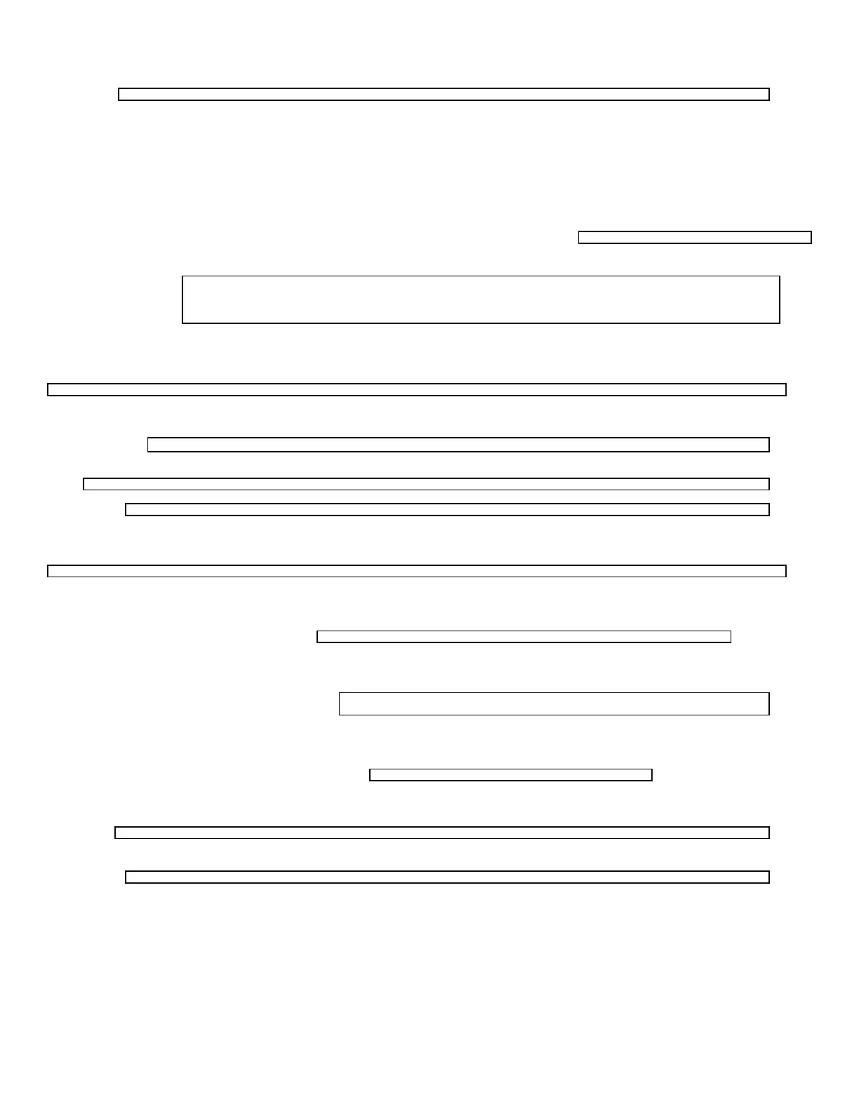
Blower is operating Replace the module board
module board and for 12vdc to red wire at call for heat. after confirming motor operation. leading to the motor.
? Yes
?
Yes Check ground wire on terminal block. -No-< Replace the motor.
?
Motor is operating -No-< Reset thermostat. Motor operating. Check -Yes-< Verify voltage thru limit and sail switch to
for 12 vdc at blue wire on molex edge module board. If circuit remains open for 30
Yes
connector. seconds, module board will go into lockout and
shut down motor. Reset thermostat. Replace defective part.
?
Check plug connection to the
creates spark and opens valve.After 15 seconds the module -No-
<
Check for 12vdc between red and yellow wires at the
module board. -Yes-< module-electrode and wire-spark gap 1/8 inch between probe and ground.
? No
?
? Check for 12vdc at limit switch, -Yes-< Replace the sail switch.
both sides.
Yes No
?
? Check for 12vdc at sail switch -Yes-< Replace the limit switch. both sides.
?
Spark occurs for approximately
7 seconds and main burner flame -No-< No spark at the electrode -No-< Replace the module.
establishes.
? Yes
? Check for 12vdc at gas solenoid -No-< Replace the module.
valve.
? Yes
?
? -No-< Check gas pressure at the manifold or for
Did the gas valve open. restrictions in the burner orifice.
? Yes No
? ?
Yes Check for restriction in
Replace the gas valve.
combustion air Intake (wasps, etc.)
? No
?
? -No- Check flame contact to electrode. Flame should
Is flame established. be hard blue.
Thermostat opens and the module board -No-< operates the fan for the Replace the module board
cool down cycle.
Yes
System Ok
SERVICE HINTS, DIAGNOSIS, AND CORRECTIVE MEASURES
FOR THE IGNITION SYSTEMS OF
SUBURBAN 24 VOLT ELECTRONIC IGNITION GAS FURNACES
WITH TIME DELAY
CAUTIONS:
1. Never operate the furnace with the electrode wire disconnected nor
with the electrode assembly removed from the furnace.
2. Never use a screwdriver on any part of the electrode assembly
while the furnace is in operation.
3. Be certain that the spark from the electrode never reaches the
flame sensor portion of the electrode assembly.
4. Be sure the electrode assembly screws are snug at all times,
especially after the electrode has been removed and reinstalled.
5. If the module board is found to be defective, it must be replaced -
it is not field repairable. Any attempts to repair the board may alter the
board and cause it to operate in an unsatisfactory manner.
6. Insure that the gap between electrode and ground is always 1/8".
The gap between the flame sensor should be approximately twice the gap
 Loading...