INSTALLATION REQUIREMENTS
WARNING! Installation of this appliance must be made in accordance with the written
instructions provided in this manual. No agent, representative or employee of Suburban or
other person has the authority to change, modify or waive any provision of the instructions
contained in this manual.
Silicone caulking is required in several places to ensure an airtight seal. Suburban
recommends using an industrial grade silicone such as Henkel Teroson SI 9160, Bostik 922,
Selleys 401 or equivalent.
NOTE: Do not install the water heater with the door facing toward the for-
ward end of the coach. See Figures 9, 10 and 11.
CAUTION:
If possible, do not install the water heater to where the vent can be covered or
obstructed when any door on the trailer is opened. If this is not possible, then the travel of the
door must be restricted in order to provide a 6” minimum clearance between the water heater
vent and any door whenever the door is opened.
CAUTION: Due to the dierences in vinyl siding, this appliance should not be installed on
vinyl siding without rst consulting with the manufacturer of the siding or cutting the siding away
from the area around the appliance vent.
CAUTION: In any installation in which the vent of this appliance can be covered due to the
construction of the RV or some special feature of the RV such as slide out, pop-up etc., always
insure that the appliance cannot be operated by setting the thermostat to the positive “OFF”
position and shutting o all electrical and gas supply to the appliance.
CAUTION: Do not install this appliance to where the vent terminates below a slide-out. This ap-
pliance is not to be installed under any overhang. It must be free and clear of any type overhang.
This appliance shall be installed only by authorised persons and in accordance
with the manufacturer’s installation instructions, local gas tting regulations, elec-
trical wiring regulations, local water supply regulations, AS/NZS 5601.2; gas in-
stallations and any other statutory regulations. Installation shall be in accordance
with AS/NZS 3500.4.
1. The appliance shall be disconnected from the gas supply piping system during
any pressure testing of the system.
2. The appliance and its gas connections shall be leak tested before placing the
appliance in operation.
3. All air for combustion must be supplied from outside the structure. Air for com-
bustion must not be supplied from occupied spaces.
4. This unit is a balance ue heater.
5. Discharge pipe must be mounted at the pressure relief valve and installed through
oor line of caravan or motor home, and must be left open to free air so as water
can escape if required and is to be installed in a continuously downward direction
and in a frost-free environment. For convenience, a break -thru grommet has
been provided in the bottom of the control housing. The center of the grommet
may be pierced and piping routed through. After drain line is installed, apply sili-
cone caulking around the grommet and drainline to ensure an air tight seal.
6. A mains pressure reducing valve must be installed in the incoming water line
with a rating of 350 kPa (50 psi). Please Note: Warranty will be void if pressure
reducing valve is not installed.
INSTALLATION INSTRUCTIONS
Keep the heater and ueway at least 25mm clear of anything that is combustible,
like walls, cupboards and timber.
Provide an opening ush with oor in outer wall of coach as shown. Wall of coach
should be framed as shown in Figure 1. Maintain inside dimensions listed below.
Do not install on carpet unless the carpet is covered by a metal shield at least
50mm greater than the width of the water heater.
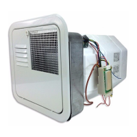
INSTALLATION USING HINGED DOOR
(See Figure 2A for models SW4DERA/SW6DERA)
(See Figure 2B for models SW4DRA/SW6DRA)
A. Remove water heater and module board from packaging.
B. In some limited accessibility applications, the chocks as illustrated in Figure
1A must be installed prior to setting water heater into position. Install chocks,
one on each side of water heater, as illustrated in Figure 1A.
C. Position heater into framed opening as illustrated.
D. On mesa or yoder type sidewalls, atten the wall area around the opening.
E. Caulk around framed opening (trailer skin) as illustrated.
F. Apply a bead of silicone caulking (or suitable caulking) around back side of
door frame. See detail “A” in illustration. This will seal frame to coach skin.
G. Push water heater into framed opening until back side of door frame (now
attached to control housing) is against the side of the coach and rmly attach
with screws around the perimeter of the frame. NOTE: The two (2) holes in
bottom of frame identied as “A” in Figure 2 are also used to mount door hinge
to the frame.
H. If already installed, conrm chocks are supporting the water heater correct-
ly. If not already completed, install chocks, one on each side of water heater,
as illustrated in Figure 1A.
I. Attach door to frame as illustrated.
J. Close the door so that the door latch protrudes through the slot in the door.
Turn latch 90 degrees to fasten door. Be sure the extension on the ue pro-
trudes through the door a minimum of 15 mm.
K. The module board is not secured to the water heater. It is to be permanently
mounted by the installer.
The module board must be mounted to where it is accessible for service yet out
of way of children. It should be located in a place where it cannot be subjected
to moisture, cleaning chemicals, ammable vapors and liquids, etc. The board
and all wiring to the board must be protected in order to prevent damages and
accidental contact with these parts. The module board may be mounted with two
(2) No. 6 x 5/8 screws or other suitable hardware.
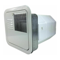
INSTALLATION USING FLUSH MOUNT
FRAME & DOOR
(See Figure 2C for models SW4DEFA/SW6DEFA)
(See Figure 2D for models SW4DFA/SW6DFA)
A. Remove water heater and module board from packaging.
B. On mesa or yoder type sidewalls, atten the wall area around the opening.
C. Caulk around framed opening (trailer skin) as illustrated.
D. Apply a bead of silicone caulking (or suitable caulking) around back side of
door frame. See detail “A” in illustration. This will seal frame to coach skin.
E. Secure intermediate door frame to trailer skin using 11 screws around the
perimeter of the frame.
F. Insert ush door frame into intermediate door frame. Pull frames tight to con-
trol housing using the three (3) No. 8-15 x 3 1/2” screws provided.
G. To install door, place the two holes in the bottom of the door over the door pins
on the frame. Close the door so that the latch protrudes through the slot in the
door. Turn latch 90 degrees to fasten door.
H. The module board is not secured to the water heater. It is to be permanently
mounted by the installer. The module board must be mounted so it is accessi-
ble for service yet out of way of children. It should be located in a place where
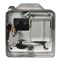
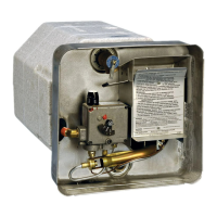
SPECIFICATIONS AND DATA FOR SUBURBAN STORAGE HOT WATER HEATER
SW4DERA
SW4DEFA
SW6DERA
SW6DEFA
SW4DRA
SW4DFA
SW6DRA
SW6DFA
1. Specications:
Capacity: 15.1 Liters 20.3 Liters 15.1 Liters 20.3 Liters
Maximum / Minimum Working Pressure: 700 kPa / 150 kPa 700 kPa / 150 kPa 700 kPa / 150 kPa 700 kPa / 150 kPa
Hourly Gas Consumption: 8.7MJ per Hour 8.7 MJ per Hour 8.7 MJ per Hour 8.7 MJ per Hour
Test Point Pressure: 2.63 kPa 2.63 kPa 2.63 kPa 2.63 kPa
Inlet Pressure 2.75 kPa 2.75 kPa 2.75 kPa 2.75 kPa
Inlet Pressure New Zealand 2.5 - 3.5 kPa 2.5 - 3.5 kPa 2.5 - 3.5 kPa 2.5 - 3.5 kPa
Jet Orice Size: .84 mm .84 mm .84 mm .84 mm
Type of Gas: Universal LPG Universal LPG Universal LPG Universal LPG
Recovery: 40 L/hr 45°C rise 40 L/hr 45°C rise 40 L/hr 45°C rise 40 L/hr 45°C rise
Electrical:
a. For Automatic Gas Ignitor 12 Volt D.C. 12 Volt D.C. 12 Volt D.C. 12 Volt D.C.
b. For Models with 240 Volt Heating Element
240 Volt 50 HZ A.C.
1440 Watts 6 Amp
240 Volt 50 HZ A.C.
1440 Watts 6 Amp
N/A N/a
2.
Location of hot water inlet is 70mm from top dead center.
Location of cold water inlet is 55mm from bottom dead center.
Location of ue outlet is 95mm from RH top edge of unit.
Location of gas inlet connection point is 40mm in from the left hand edge of the control housing.
3. Size of inlet 3/8”
DO NOT PLACE ARTICLES ON OR AGAINST THIS APPLIANCE.
DO NOT USE OR STORE FLAMMABLE MATERIALS NEAR THIS APPLIANCE.
DO NOT SPRAY AEROSOLS IN THE VICINITY OF THIS APPLIANCE WHILE IT IS IN OPERATION.
DO NOT MODIFY THIS APPLIANCE.
2
 Loading...