____________________________________________________________________________________
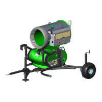
Operating Manual access/eco/peak/power/silent Page
20
4
D
EFECTS -
C
AUSES -
S
OLUTIONS
4.1. Tripped motor protection for fan: F1
Possible reasons:
Increase of current consumption, caused by undervoltage, a too strong
decrease in voltage (minimum operation voltage 360 VAC), defective
change-over relay star-delta or phase failure.
Let the voltage at the entry terminals be checked by experts! The loss of
voltage is calculated from the cable length, the conductive material, the
conduction cross section and the load (current consumption). Therefore the
real loss of voltage can only be measured when all machines are in
operation.
Blocking of the fan protection grating by ice also leads to an increased
current consumption.
Solution:
Remove cause of the failure, switch off the fan, press the reset button of the
motor protection switch F1 (fan) again and restart the machine.
4.2. Tripped motor protection for compressor: F2
Possible reasons:
Increase of current consumption caused by under voltage, a too strong
decrease in voltage (minimum operation voltage 360 VAC), phase failure,
overpressure or mechanical damage.
Solution:
After elimination of the failure press the reset button of the motor protection
switch F2 (compressor) and start the machine again.
Warning: the motor protection switches should not be pressed repeatedly within a
short time, without having eliminated the source of the failure, as this consequently
leads to a BURN OUT of the motor windings.
4.3. Tripped breaker for heating: F4 and Q1 resp. F3 and Q1 for Compact-Peak
Possible reasons:
Defective heating caused by short circuit (automatic cutout F4 resp. F3) or
accidental ground (leakage current relay Q1).
For locating the defect, switch off each heating step by step (nozzle ring
heating 1, nozzle ring heating 2, valve block heating above, valve block
heating below).
The nozzle ring heating is wired via disconnect terminals; in the electric box
this heating can be taken off the power supply system by opening the
terminals. The valve block heating is connected in the terminal box at the
upper side of the valve block.