Do you have a question about the Sullair RH Series and is the answer not in the manual?
Provides essential safety guidelines for operating the dryer, emphasizing compliance with regulations and safe practices.
Outlines critical safety rules for dryer installation, operation, maintenance, and repair procedures.
Lists crucial safety notes for dryer operation, emphasizing safe working methods and regulations.
Details installation procedures, emphasizing the need for authorized personnel and optional fittings.
Lists essential preparatory steps before operating the dryer, including manual review and safety checks.
Details maintenance and repair procedures to be performed only by qualified and trained technicians.
Outlines routine maintenance tasks for the end-user, such as keeping the dryer clean and checking drains.
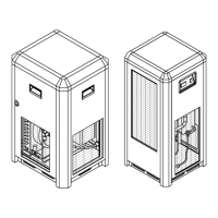
Describes key components and features of the refrigerant dryer, including compressor, condenser, and protection.
Details the overload protector and high pressure security switch that protect the refrigerant circuit.
Provides step-by-step instructions for starting and shutting down the dryer for the first time and daily.
Provides the electrical wiring diagram for the RH series, detailing component connections.
Lists common problems, possible causes, repair steps, and comments for troubleshooting dryer issues.
Covers safety regulations, issues to avoid, receiving inspection, and transportation guidelines.
Highlights modifications that void warranty and improper air usage precautions.
Explains the refrigerant and compressed air circuits and their operational principles.
Warns to verify operating parameters, check unit integrity post-shipment, and ensure qualified personnel startup.
Provides emphasized instructions for mechanical construction, local regulations, and filter installation.
Lists crucial preparatory steps before operating the dryer, including manual review and parameter checks.
Details the sequence of operations for first start-up, shutdown, and general dryer operation.
Provides specific procedures for starting and shutting down the dryer, including warnings on frequent cycling.
Provides the electrical wiring diagram for RN5-10-15-20-25 models.
Provides the electrical wiring diagram for RN30-50-75-100 models.
Provides the electrical wiring diagram for RN125-150 models.
Provides the electrical wiring diagram for RN175 models.
Provides the electrical wiring diagram for RN200 models.
Provides the electrical wiring diagram for RN250-325 models.
Electrical wiring diagram for RN250-325 models operating at 230V, 3-phase, 60Hz.
Detailed wiring diagram for RN250-325 models at 230V, 3-phase, 60Hz.
Wiring diagram for RN250-325 models operating at 460V/3-phase/60Hz or 400V/3-phase/50Hz.
Detailed wiring diagram for RN250-325 models at 460V/400V.
Covers maintenance procedures for engineers/technicians and users, including recommended schedules.
Details maintenance tasks for qualified technicians, emphasizing safety and proper tools.
Outlines routine maintenance tasks for the end-user, such as cleaning and drain checks.
Lists common problems, their causes, repair steps, and relevant comments for diagnosing issues.
Explains the front panel layout, buttons, and basic operational screens of the E-680 controller.
Describes the normal operation screen display, navigation, and status indicators of the E-680 controller.
Outlines how to enter and navigate the controller's configuration mode, set parameters, and adjust security code.
Provides the electrical wiring diagram for RD400 models operating at 230V, 3-phase, 60Hz.
Detailed wiring diagram for RD400 models at 230V, 3-phase, 60Hz, listing component functions.
Wiring diagram for RD400 models operating at 460V/3-phase/60Hz or 400V/3-phase/50Hz.
Detailed wiring diagram for RD400 models at 460V/400V, listing component functions.
Wiring diagram for RD500/700 models operating at 230V, 3-phase, 60Hz.
Detailed wiring diagram for RD500/700 models at 230V, 3-phase, 60Hz, listing component functions.
Wiring diagram for large RD models operating at 460V/400V.
Detailed wiring diagram for large RD models at 460V/400V (W), listing component functions.
Wiring diagram for RD700-850 models at 230V, 3-phase, 60Hz (W).
Detailed wiring diagram for RD700-850 models at 230V, 3-phase, 60Hz (W), listing component functions.
Wiring diagram for large RD models at 460V/400V (W).
Detailed wiring diagram for large RD models at 460V/400V (W), listing component functions.