Section 2
DESCRIPTION
5
2.1 INTRODUCTION
Your new Sullair flood-lubricated Rotary Screw
Vacuum System, provides you with superior per-
formance and greatly reduced maintenance.
Compared to other vacuum pumps, the Sullair
Rotary Screw is unique for its reliability and lack of
wear. The vacuum unit requires absolutely no
inspection of its internal parts.
Read Section 6 (Maintenance) to keep your
Vacuum System in top operating condition. Should
any problem or question arise which cannot be
answered in this text, contact your nearest Sullair
representative or the Sullair Corporation Service
Department.
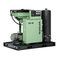
2.2 DESCRIPTION OF COMPONENTS
Refer to Figures 2-1A, 2-1B, 2-1C, 2-1D, 2-2A, 2-
2B, 2-3, and 2-4. The components and assemblies
of the VS-16 Series Vacuum System is clearly
shown. A complete package includes vacuum unit,
electric motor, starter, inlet system, discharge sys-
tem, lubrication and cooling system, capacity con-
trol system and instrumentation.
On air-cooled models, an electric motor-driven fan
pushes air through the cooler (mounted at the top
of the machine), thereby removing the heat of com-
pression from the cooling fluid.
On water-cooled models, a shell and tube heat
exchanger is mounted on the control panel sup-
ports. Fluid is piped into the four-pass exchanger
where the heat of compression is removed from
the fluid.
The "open" design of the VS-16 Series Vacuum
Pump (whether air-cooled or water-cooled), pro-
vides easy access to all components.
2.3 ROTARY SCREW VACUUM SYSTEM, FUNC-
TIONAL DESCRIPTION
The Sullair Vacuum System utilizes the rotary
screw, single stage, positive displacement flood-
lubricated type of vacuum unit. It provides a contin-
uous (pulse-free) vacuum to meet your needs.
Fluid is injected into the vacuum unit where it mixes
directly with the gas as the internal rotors turn draw-
ing a vacuum. The fluid flow has three basic func-
tions:
1. As coolant, it controls the rise of air tem-
perature normally associated with the heat
of compression.
2. It seals the leakage paths between the
rotors and the stator and also between the
rotors meshes.
3. It acts as a lubricating film between the
rotors allowing one rotor to directly drive the
other (an idler).
After the gas/fluid mixture has been discharged
from the vacuum unit, the fluid is separated from
the gas. At this time, the gas is discharged from the
separator tank and the fluid is cooled in preparation
for reinjection.
2.4 COOLING AND LUBRICATION SYSTEM, FUNC-
TIONAL DESCRIPTION
Refer to Figure 2-2A or 2-2B. The cooling and lubri-
cation system (air-cooled version) consists of a fan,
fluid pump, pump suction strainer, radiator-type
cooler, main line filter, cooler thermal bypass valve,
fluid pressure relief valve and interconnecting pip-
ing and tubing.
For the water-cooled models, a shell and tube heat
exchanger and water-flow regulating valve are sub-
stituted for the radiator-type cooler listed above.
The unit-driven fluid pump causes fluid flow by
drawing the fluid from the sump and forcing it to an
area of lower pressure in the vacuum unit. Proper
fluid pressure at the vacuum unit is ensured by a
pressure regulator which is located downstream of
the fluid filter.
On air-cooled models, the fluid is pumped from the
receiver/sump to the thermal valve. The thermal
valve has a nominal temperature of 170ºF (77ºC).
At low temperatures, the fluid passes through the
thermal valve, the filter and directly to the vacuum
unit. As the discharge temperature rises above
170ºF (77ºC), due to the heat of compression, the
cooler bypass valve begins to close and a portion of
the fluid then flows through the cooler; from the
cooler to the filter, and on to the vacuum unit.
On water-cooled models, a water-flow regulating
valve will regulate the amount of cooling water nec-
essary to maintain the proper operating tempera-
ture. When the fluid leaves the sump it is pumped
to the cooler. Depending on the temperature of the
fluid, the water-flow regulating valve allows the
proper amount of cool water to enter the cooler and
remove the heat of compression from the fluid.
From the cooler, the fluid then flows through the fil-
ter and on to the vacuum unit.
A Sullair Vacuum System requires no
inspection and/or maintenance of its inter-
nal parts with the limits of the binding war-
ranty.
 Loading...