Do you have a question about the Sullair VS16 40HP Series and is the answer not in the manual?
Required PPE for safe operation and maintenance of the system.
Steps for safely releasing internal system pressure before servicing.
Safety measures to prevent fires and explosions during operation.
Identification of hazards from moving components and safety precautions.
Guidance on avoiding injury from hot surfaces and sharp parts.
Handling hazardous materials and necessary ventilation guidelines.
Essential safety measures to prevent electrical hazards.
Proper techniques for lifting and moving the vacuum system safely.
Explanation of how the rotary screw vacuum unit operates.
How the cooling and lubrication systems function within the unit.
How the system's control logic manages operational functions.
Detailed technical specifications for VS-16 30-50HP models.
Guidelines for proper mounting and foundation preparation.
Step-by-step guide for the initial startup of the machine.
Scheduled maintenance tasks for 4000-hour intervals.
Procedures for replacing system components and making adjustments.
Steps for changing separator elements for different models.
Common symptoms, causes, and corrective actions for system issues.
Electrical schematic for VS-16 MFV single control annunciation.
Electrical schematic for VS-16 MFV dual control MCP28.
Electrical schematic for VS-16 MFV dual control systems.
Electrical schematic for VS-16 SSRV dual control systems.
| Brand | Sullair |
|---|---|
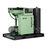
| Model | VS16 40HP Series |
| Category | Accessories |
| Language | English |