Do you have a question about the Sullivan-Palatek VFD Series and is the answer not in the manual?
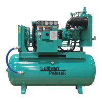
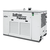
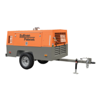
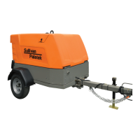
Introduces the new line of Sullivan-Palatek rotary screw compressors and their capabilities.
Provides essential safety precautions for operating and maintaining the air compressor.
Outlines the structure of the manual, detailing the content of each section for easy navigation.
Indicates where to find additional detailed information on specific components or optional equipment.
Details critical safety guidelines for the proper operation and maintenance of air compressors.
Explains the purpose and location of warning decals designed to identify potential hazards.
Describes the availability and warranty of factory-remanufactured airends for screw compressors.
Presents detailed technical specifications for various compressor models and configurations.
Provides a visual representation of the physical dimensions for air-cooled compressors.
Offers a visual overview of the physical dimensions for larger air-cooled compressor models.
Illustrates the pneumatic and fluidic connections for air-cooled compressor systems.
Details the pneumatic and fluidic connections specific to water-cooled compressor systems.
Shows the electrical circuit layout for compressors with specific fan motor configurations.
Presents the electrical wiring schematic for compressors with larger fan motor sizes.
Details the main systems comprising the air compressor package.
Explains the process of air compression within the rotary screw unit.
Describes the components responsible for powering and operating the compressor.
Identifies and explains the function of various safety and protective components.
Details the system responsible for separating and discharging air and oil.
Explains the operation of the systems that manage oil circulation and heat dissipation.
Describes how the compressor regulates air intake and adjusts capacity based on demand.
Provides guidance on inspecting the compressor unit upon delivery for any shipping damage.
Details safe procedures and equipment required for moving and lifting the compressor.
Offers recommendations for selecting a suitable installation site and ensuring proper support.
Specifies requirements for supplying clean and cool intake air to the compressor.
Outlines ventilation requirements to maintain optimal operating temperatures for the compressor.
Provides instructions for making safe and compliant electrical connections to the compressor.
Explains how to verify the correct fluid level before initial compressor startup.
Details how to check and ensure the correct motor rotation to prevent damage.
Guides on connecting the compressor to the plant air system and related components.
Addresses considerations for installing and sequencing multiple compressors.
Provides procedures for safely storing the compressor for extended periods.
Describes the T1 microprocessor interface, including keypad and LED indicators.
Explains how to use access codes to navigate restricted menu pages on the controller.
Lists essential checks and preparations required before starting the compressor.
Details the step-by-step procedure for starting the air compressor under normal conditions.
Provides the correct procedure for safely shutting down the air compressor.
Outlines procedures for safely restarting the compressor after unexpected shutdowns.
Presents a comprehensive schedule of required maintenance tasks based on operating hours.
Covers fundamental safety rules and precautions for performing maintenance.
Details the critical lockout/tagout and isolation procedures before maintenance.
Provides recommended torque values for various fasteners based on size and grade.
Details lubricant types, checking levels, filling, changing, and conversion procedures.
Explains the procedure for replacing the oil filter element at recommended intervals.
Provides instructions for replacing the air/oil separator element.
Describes inspection, cleaning, and installation procedures for the oil/after cooler.
Details inspection and cleaning procedures for the minimum pressure valve.
Explains how to adjust pressure settings for load, unload, and modulation.
Lists common causes and remedies for a compressor failing to start.
Identifies issues preventing the compressor from reaching its target discharge pressure.
Addresses reasons for the compressor shutting down while air demand is present.
Explains causes for line pressure exceeding the compressor's unload setting.
Details potential causes and solutions for high lubricant usage.
Troubleshoots scenarios where the pressure relief valve activates frequently.
Addresses issues related to receiver pressure venting during the blow-down process.
Provides information and contact details for ordering replacement parts and manuals.
Features exploded drawings of assemblies and sub-assemblies for part identification.
Lists recommended spare parts to maintain minimal downtime for common maintenance.
Details various compressor lubricant options, their properties, and ordering information.
Exploded view and parts list for the main compressor unit, frame, and drive components.
Diagrams and parts lists for electrical control box assemblies for different motor configurations.
Parts breakdown for pneumatic and electrical control systems for various HP ranges.
Parts lists for remote electrical/pneumatic control assemblies in NEMA 1 and NEMA 4 enclosures.
Exploded views and parts lists for standard and remote air inlet assemblies.
Diagram and parts list for the receiver tank and its associated components.
Parts lists and diagrams for air piping configurations for various compressor models.
Parts lists for air cooler assemblies across different horsepower ratings.
Details the components for the water cooler assembly.
Provides a parts list and diagram for the water piping system.
Lists components for air-cooled and water-cooled fluid piping systems.
Parts lists for air-cooled and water-cooled enclosure assemblies.
| Brand | Sullivan-Palatek |
|---|---|
| Model | VFD Series |
| Category | Air Compressor |
| Language | English |