Do you have a question about the Sumake SF501 and is the answer not in the manual?
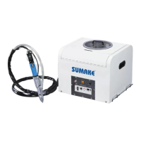
The SUMAKE SF501 and SF502 are automatic screw suppliers designed for professional and industrial use, aimed at improving screw driving speed, stability, and efficiency. These devices integrate pneumatic or electric screwdrivers, high-tech automatic feeders, and high-precision jaws to provide a stable and efficient operation. They are customizable with particular screw and working environment, and optional pneumatic screwdriver models are available.
For the SF501 model:
For the SF502 model:
The installation process involves connecting the screw delivery hose, air hose, and signal cable to the feeder unit. It is crucial to ensure that the signal cable and air hose do not come into contact with the hook or balancer wire to prevent excessive bending or twisting of hoses and cables, which could cause damage or disconnection. For pneumatic screwdrivers, the delivery hose and air hose need to be connected. For electric screwdrivers, the delivery hose and the wire of the electric screwdriver are connected.
The feeder unit should be connected to a compressed air source with an air pressure of 4-5 kg/cm². The air pressure needs to be adjusted using the air source adjustment knob. The screw delivery timer setting on the front of the feeder unit should be checked, with a standard operation setting of approximately 0.5. Finally, the power cord is connected to a single-phase AC-220 wall outlet.
To begin, open the machine cover and load screws into the hopper, ensuring the maximum volume is utilized. Turn on the power switch and verify that the power and VFD lights are "ON". The feeding action should then be checked. A single cycle will send a signal from the driver unit to the feeder, causing the escapement to release one screw into the chute for delivery to the driver's tip via compressed air. The first cycle may have a 3-5 second delay. A critical safety warning advises against pointing the driver tip toward a person, as a screw might accidentally shoot out, causing injury.
For pneumatic screwdrivers, normal operation is confirmed by checking screw feeding and rotation. For electric screwdrivers, the normal operation is checked based on the type:
The torque setting for both pneumatic and electric screwdrivers should be verified. This involves fitting the driver tip over the screw hole, performing a test fastening, and ensuring the screw is driven into the hole and fastened to the specified torque. The driver must be held vertical to the work surface, and the delivery hose should be free of twists and bends.
After preparatory steps are completed, load mass screws into the hopper and turn on the power switch. Hold the driver unit and manually press the Y-pipe to confirm that a screw is seen at the tip of the driver for the first time. Align the screw at the driver tip vertically with the screw hole of the work-piece. Then, repeat the steps to tighten subsequent screws.
If satisfactory screw delivery cannot be achieved through time adjustments, the screw delivery air volume must be reset. This is done by turning the switch rod adjustment screw on the right side of the feeder escapement. First, use a wrench to release the nut. Then, adjust the screw: clockwise to decrease air volume, and counter-clockwise to increase air volume. After adjustment, tighten the nut.
If the escapement shutter malfunctions, its speed needs to be adjusted. For rightward speed, adjust the right valve. For leftward speed, adjust the left valve.
To adjust the torque, release the nut, pipe cover, pipe spring, and Y pipe. Use a PH driver to insert into the hole and adjust the torque range by turning. Lubricate the screwdriver after adjusting, then reassemble the pipe spring, pipe cover, and Y pipe, ensuring the pipe spring is inside.
Release the nut, pipe cover, pipe spring, and Y pipe. Turn the knob to adjust the torque range (left or right). Lubricate the pipe cover after adjusting, then reassemble the adapter-pipe spring-pipe cover-Y pipe, ensuring the pipe spring is inside.
For pneumatic screwdrivers, lubrication is essential. Allow 3 to 5 drops of oil to flow through the window, then retighten the needle valve. Idle the driver unit for one or two minutes to allow the oil to circulate. After completing operations, turn off the power switch.
To replace the BIT, first release the nut, disassemble the pipe cover, pipe spring, and Y pipe. Use a negative driver to push the ring forward, then pull out the old BIT. While still pushing the ring forward, insert the new BIT. Lubricate the components and reassemble.
Release the nut, pipe cover, pipe spring, and Y pipe. Pull out the latch and remove the damaged BIT, then insert the new BIT. Lubricate after finishing and reassemble the adapter-pipe spring-pipe cover-Y pipe, ensuring the pipe spring is inside the adapter and pipe cover.
Note: If the screwdriver set isn't working smoothly, it might be due to the circlip. The normal reason is "Ms. Plate" with "Circlip" not matching. If this issue occurs, release the screws of the delivery switch set, then make sure the circlip is located in the middle of Ms. Plate, and then reassemble.