10
The hollow shaft is made according to the tolerances of JIS H8. If you experience
impact or notice a large radial load with the hollow shaft, further tighten the fitting
between the hollow shaft and the driven shaft. (We recommend JIS js6 or k6 as the
tolerance of a driven shaft.)
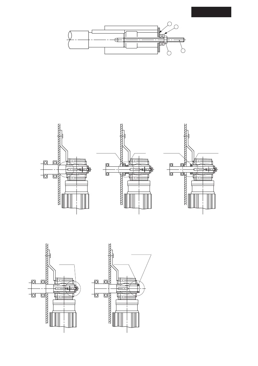
Fig.2 Jig
a………Spacer c………Nut
b………Thrust Bearing d………Bolt
(b-1) Method to avoid the Drive from slipping away from a driven machine. (Fig.3–5)
(03#, 07#, 17#, 1010#)
Fig.3 Fixed by spacer and plate Fig.4 Fixed by end plate Fig.5 Fixed by set screw and
stopper ring
Method to avoid the Drive from slipping reactor to a driven machine. (Fig.6–7)
Fig.6 Fixed by spacer Fig.7 Fixed by set screw