12
(a–2) How to set the shaft (1110#-1640#)
Apply molybdenum disulfide grease to the surface of a driven shaft and the inner
surface of a hollow shaft. Then insert the Drive into the driven shaft.
If the fitting is too tight, lightly knock the end face of a hollow output shaft with a wooden
hammer for smooth insertion. Do avoid knocking the casing. We recommend making a
jig shown Fig 9. Using this jig, you can insert the Drive smoothly.
The hollow shaft is made according to the tolerances of JIS H8. If you experience
impact or notice a large radial load with the hollow shaft, further tighten the fitting
between the hollow shaft and the driven shaft, (We recommend JIS js6 or k6 as the
tolerance of a driven shaft.)
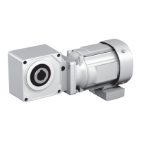
Fig.9 Jig
a………plate d………Nut
b………Spacer e………Bolt
c………Thrust Bearing
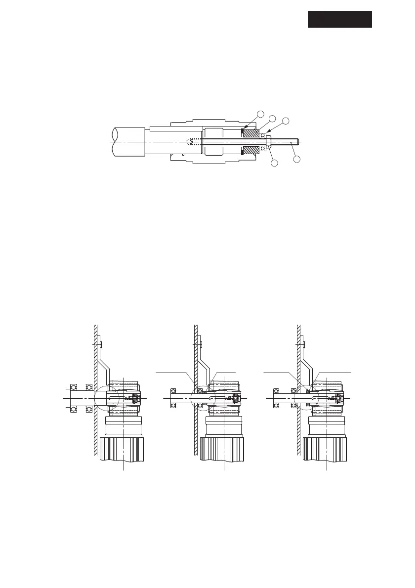
(b–2) Method to avoid the Drive from slipping away from a driven machine. (Fig.10–12)
(1110#-1640#)
Fig.10 Fixed by spacer and plate Fig.11 Fixed by end plate Fig.12 Fixed by set screw and
stopper ring