14
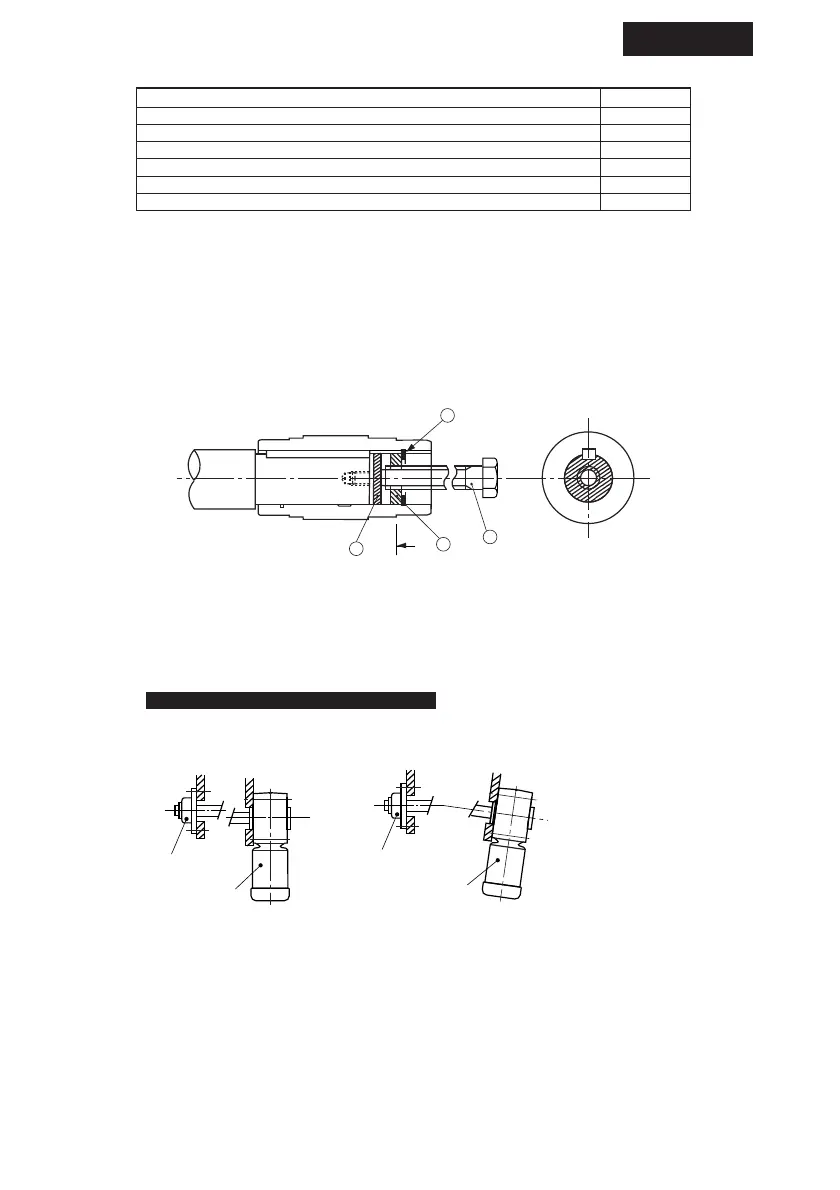
(d–2) How to remove the shaft (1110#-1640#)
Make sure that excess force does not act on the Drive and shaft. Using a jig as shown
in Fig. 17 will facilitate removal of the shaft.
Parts for setting, securing or removing the shaft should be prepared by the user.
Fig.17 Removing Jig
f………Spacer h………Plate
g………Bolt i………Shaft retaining c-ring
(2) Flange and On-bed mounting (Standard)
When installing the Drive, pay attention to the alignment between the Drive and shaft to
be driven so that the Drive is free from excess force.
Fig.18 Flange coupling
Bearing unit
Bearing unit
HYPONIC DRIVE
hollow shaft type
(The concentricity between the
shaft and spigot joint is out of
allowable range.)
(The shaft centerline is not
positioned at right angles to the
flange.)
HYPONIC DRIVE
hollow shaft type
Bad example Bad example
COMMON
Table 4 Size of hexagon socket head bolt
Frame size Bolt
M61110#, 1120#
M8
M10
1210#, 1220#, 1230#, 1240#
M12
1310#, 1320#, 1330
#
, 1340#, 1410#, 1510#
M16
M20
1420#, 1430#, 1440#, 1520#, 1521#, 1522#, 1634#
1530#, 1531#, 1540#
1630#, 1631#, 1632#, 1633#, 1640#
4. Installation