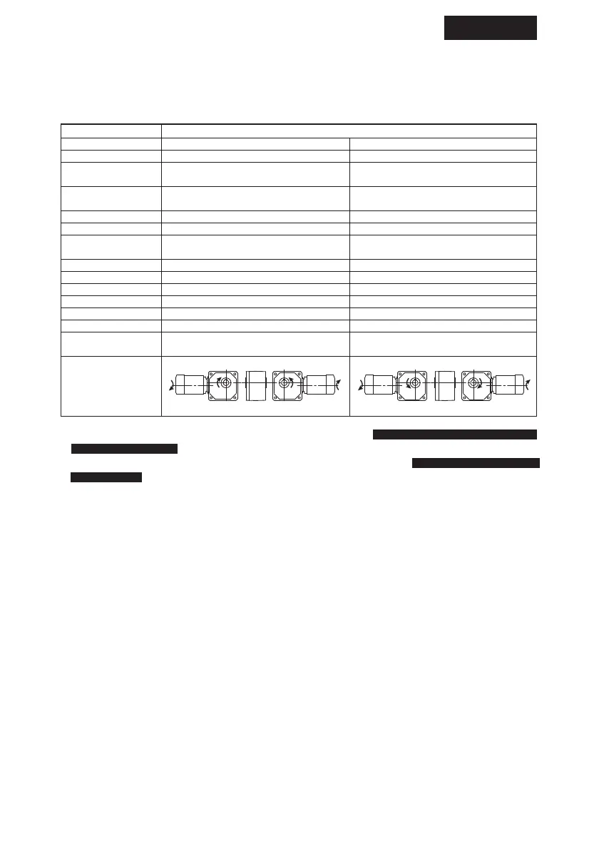
5–1) Confirming Rotation Direction
Figure 19–21 shows the rotation direction of the output shaft when wires are connected as
shown in Fig. 28–32 on page24–34.
Fig.19 Rotation direction of slow speed shaft (RNYM Series)
· Change over the SW shown in Fig.29, 32 to reverse the rotation of 15-90W Single-phase motor, Single-
phase reversible motor
.
· Change the positions of R and T shown in Fig.28, 30 to reverse the rotation of
3-phase motor, 3-phase high
efficiency motor
.
16
COMMON
Framesize
Rotationdirection
Reductionratio
03#,07#
17#
1010#,1110#,1210#
1310#,1410#,1510#
1120#,1220#,1320#
1420#,1520#
1521#
1522#
1230#,1330#
1430#,1530#
1531#
1630#
1631#
1632#
1633#
1634#
1240#,1340#,1440#
1540#,1640#
5,80,100,120,160,200,240
5,7.5,10,12,80,100,120,150,200,240
-
5,7,10,12,15,20,25,30,40,50,60
5,7,10,12,15,20,25
5,7,10,12,15
-
-
-
-
30
20,25
5,7,10,12,15
300,360,480,600,720,900,1200,1440
7.5,10,12,15,20,25,30,40,50,60
15,20,25,30,40,50,60
5,7,10
-
-
-
80,100,120,150,200,240
40,50,60,80
80,100,120
150,200,240
40,50
30,40
20,25
-
5. Coupling with Other Machines