COMMON
5–2) Coupling Installation
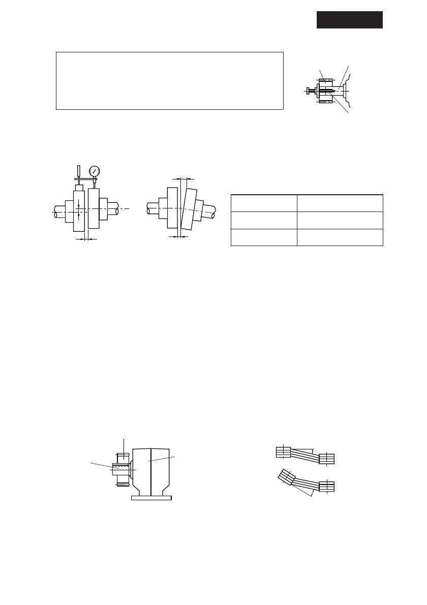
A Dimension
Tolerance
B Dimension
Tolerance
X
dimension
0.1mm or manufacturer
,
s
specification
0.1mm or manufacturer
,
s
specification
manufacturer
,
s
specification
Table 5 Centering accuracy of flexible coupling
(2) When using a Chain Sprocket and Gear
· The chain tension angle should be perpendicular to the shaft.
· Refer to the chain catalog for the chain tension.
· Select sprockets and gears whose pitch diameter are three times the shaft diameter or
greater.
· Install sprocket and gears so that their point of load application will be closer to the
gearmotor side with respect to the length of the shaft. (Fig.24)
(3) When using a V-belt
· Excessive V-belt tension will damage the shaft and bearing. Refer to the V-belt catalog for
proper tension.
· The parallelism and eccentricity (ß) between two pulleys should be within 20
,
. (Fig25)
· Use a matched set with the same circumferential length when more than one belt is to be
installed.
· When installing a coupling, do not impact or apply excessive
thrust load to the shaft; otherwise, the bearing may be
damaged.
· Thermal shrinking or end cap screws are recommended for
mounting (Fig.22).
(1) When using a Coupling
The accuracy of the dimensions (A,B,and X) shown in Fig.23
should be within the toleronce shown in Table 5.
5. Coupling with Other Machines