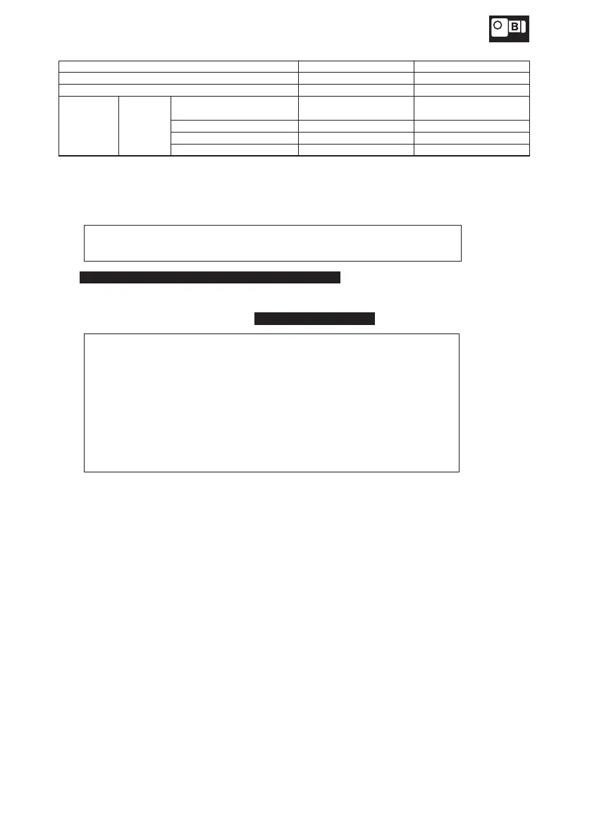
Input power AC200V–230V AC380V–460V
Rated voltage of varistor AC260V–AC300V AC510V
Voltage of varistor 430V–470V 820V
Rated power
of varistor
Brake type
SB-004, FB-01A1, 02A1,
05A1
0.25Watt or more 0.4Watt or more
FB-1D 0.4Watt or more 0.6Watt or more
FB-2D, 3D, 5B, 8B
FB-10B1, 15B1
0.6Watt or more
1.0Watt or more
1.0Watt or more
1.0Watt or more
Table 9 Varistor (VR) Capacity
· The brake delay time of the normal braking action is different from that of the fast braking
action. Table 1 on page 6 shows the delay time. Use a circuit that meets your requirements.
· DC braking capacity (for DC coil loading) exceeding 5 times the braking current shown on
the name plate is recommended for the fast braking action.
· Use fast braking action for lifting devices or for better stopping accuracy.
· Use fast braking action when a leading capacitor is used.
·
For 15W–90W single-phase capacitor run type motor , connect the accessory capacitor,
(see Table 7 on page 23 for the capacitor.)
· Pay attention to the following items when driving an inverter .
· For the inverter-driven motor with a brake, use the primary-side power
supply for braking as shown in Fig.31, and synchronize the braking
operation with the ON/OFF operation of the unit.
· For the inverter-driven motor with a brake, interlocking with the inverter
is necessary to engage/release the MC. Refer to the inverter
maintenance manual or guide.
· During the low speed running, the mechanical life might be in danger of
being shortened by reducing the cooling ability.
· When it happens, please reduce the time that brake's power is on.
35
6. Wiring