Troubleshooting
Automatic Restarting After a Helium High Temperature Shutdown Error
If a helium discharge high temperature shutdown error causes a shutdown of the system, the
compressor will attempt to restart itself 5 times at 20 minute intervals before a reset signal must
be provided to the compressor. A reset signal or power outage will clear the shutdown error
and reset the automatic restart counter.
If the system is set for DB25 Configuration Mode 2 and a helium high temperature shutdown
error occurs, the system will ignore automatic resets during the first 19 minutes of the 20
minute interval to prevent rapid on-off cycling of the compressor.
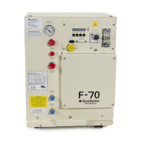
System Status Display
Normal conditions: When all systems are operating normally, with no system errors, the
following lines are displayed on the LCD in the order listed below by scrolling the display. Press
the DISPLAY buttons (up and down arrows) to scroll the LCD. Scrolling past the bottom of the
display will start back at the top and repeat. If the DISPLAY button is pressed and not pressed
again after 30 seconds, the display will return to the first line (ET).
Elapsed time in hours to one decimal place and control state
Helium Temp-OK
Water Temp-OK
Water Flow-OK
Motor Temp-OK
Phase Seq (sequence)-OK
Return Press-OK
Ads Life XXXXX
DB-25 Config (switch configuration)-OK
Rtn Press (current return pressure)
Software Version
Cold Head Run (When in OFF state only)
Error conditions: If a system error occurs that causes an alarm or shutdown condition, the
monitor point as listed above will change from “OK” to “ERR” and that monitor point will be
scrolled to the top for display.
Any point that has not failed will continue to display OK if the operator manually scrolls the
display.
If additional points fail before the operator resets the first error(s), the latest point to fail will
change from “OK” to “ERR” and will be scrolled to the top for display. In this way, the operator
will see the most recent fault displayed on the LCD and, by manually scrolling the display, can
see other error conditions that lead up to the latest.
If a monitoring sensor is disconnected, the display for that monitor point will change from “OK”
to “FAIL”.
Error Conditions
An error condition will cause either a system alarm or a shutdown. The following table lists the
alarm and the shutdown errors that are monitored. Overload trip of the Mains Power switch
(described below) is not monitored or reported.