Do you have a question about the Summit HM2-08-SBC and is the answer not in the manual?
Lubricate and install fittings into manifold valve ports, including ISO couplers and male tips.
Install manifold valve assembly onto tractor's remote outlet, adjusting spacing as needed.
Route cable and connect switch box to manifold solenoids and tractor power source.
Explains how to select circuits 1 or 2, and combine them using the rocker and push button switches.
Safety warnings regarding pressure and proper connection to tractor remote outlet.
Provides solutions for valve not working, previous operation failure, or only one circuit functioning.
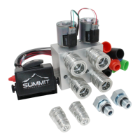
The Summit Hydraulics Hydraulic Multiplier, Model: HM2-08-SBC, is a device designed to expand the hydraulic capabilities of a tractor by allowing a single remote outlet to control multiple hydraulic circuits. This multiplier essentially acts as a selector, enabling the operator to switch between different hydraulic functions without needing additional remote outlets on the tractor. It is particularly useful for agricultural or industrial applications where multiple hydraulic implements are used, but the tractor has limited hydraulic ports.
The core function of the hydraulic multiplier is to provide two independent hydraulic circuits (Circuit 1 and Circuit 2) from a single tractor remote outlet. This is achieved through a valve manifold (HM2-08) equipped with two HD Solenoid Coils. When the multiplier is connected to the tractor's remote outlet, the flow of hydraulic fluid from the tractor can be directed to either Circuit 1 or Circuit 2 based on the operator's selection.
The selection is managed by a Lighted Rocker Switch Box Control. This control box contains two switches: a large lighted rocker switch and a red push-button toggle switch. The rocker switch allows the operator to select between Circuit 1 and Circuit 2. When the rocker switch is pressed to the left, Circuit 1 is activated; when pressed to the right, Circuit 2 is activated. Once a circuit is selected, the tractor's remote lever then directs the flow of oil to that specific circuit, controlling the attached implement.
A unique feature of this multiplier is its ability to "combine" both circuits. The red push-button toggle switch on the side of the switchbox enables the simultaneous operation of Circuit 1 and Circuit 2. This can be advantageous for implements that require synchronized hydraulic actions or for specific tasks where dual circuit operation is beneficial. The valve is designed for both continuous and intermittent operation, offering flexibility for various applications.
The hydraulic multiplier connects directly into the tractor's remote outlet using adjustable eccentric fittings and ISO Male Tips. These fittings are designed to accommodate varying spacing of tractor SCV (Selective Control Valve) ports, typically adjusting from 2" to 2-1½". An optional Adapter Kit (AK-08S) is available for tractors with wider port spacing, allowing adjustment from 1-1½" to 8". This adaptability ensures compatibility with a broad range of tractor models.
The system includes ISO Couplers (four in total) for connecting external hydraulic lines to the multiplier's output circuits (1A, 1B, 2A, and 2B). These couplers facilitate quick and secure connections to hydraulic implements. The power for the solenoid coils and the control box is drawn from the tractor's electrical system, requiring a keyed power source that is "hot" only when the engine is running, and a clean metallic surface for grounding.
The installation process is straightforward, emphasizing proper connection and adjustment for optimal performance. Before installation, all threads and O-Rings should be lubricated with hydraulic fluid. The manifold valve ports are 3/4-16 SAE straight thread, and Teflon tape or pipe dope should not be used. Female ISO quick couplers are installed in ports 1A, 1B, 2A, and 2B. Male ISO tips are then installed onto the eccentric fittings, which are subsequently attached to the manifold body ports P1 and P2. The jam nuts on these fittings are left loose initially to allow for spacing adjustment.
Once the fittings are in place, the manifold valve assembly is inserted into the tractor's remote outlet. The male tips are adjusted to match the spacing of the remote outlet, and the valve is firmly pushed into place, using the SCV release lever if necessary. After the valve is seated, the jam nuts are tightened to 35 ft-lbs.
The control switch box is mounted to or near the SCV lever that controls the tractor's remote valve. A grey cable with two connectors routes from the switch box to the manifold. The green and black wired connector connects to the Circuit 1 solenoid (labeled SV1), and the red and white wired connector connects to the Circuit 2 solenoid (labeled SV2). The red power wire from the switch box is connected to a keyed power source, and the black wire is attached to a clean metallic surface for ground.
Operation is intuitive: the lighted rocker switch selects the desired circuit, and the tractor's remote lever then controls the hydraulic flow for that circuit. The red push-button switch provides the flexibility to combine both circuits for simultaneous operation. This design allows for efficient management of multiple hydraulic functions from a single tractor control, enhancing productivity and reducing the need for constant re-plumbing of hydraulic lines.
The manual provides important warnings and troubleshooting guidelines to ensure the longevity and safe operation of the hydraulic multiplier. A critical warning states: "DO NOT LOOSEN OR REMOVE ANY FITTINGS, COUPLERS OR VALVE CARTRIDGES WHILE THE SYSTEM IS UNDER PRESSURE OR WHILE A LOAD IS BEING HELD UP BY THE VALVE." This emphasizes safety and the importance of depressurizing the system before any maintenance or adjustments.
Troubleshooting steps are clearly outlined for common issues:
Regular maintenance involves ensuring all connections are secure and free from leaks. Lubricating threads and O-rings during installation helps prevent wear and ensures a tight seal. The design of the system, with its modular components like solenoids and cartridges, allows for targeted replacement of parts, simplifying repairs and extending the life of the multiplier. The use of standard ISO couplers also facilitates easy connection and disconnection of implements, reducing wear on the main unit. Adhering to the specified torque for jam nuts (35 ft-lbs) is crucial for maintaining the integrity of the connection to the tractor's SCV.
| Power Input | 5V DC |
|---|---|
| Standards | IEEE 802.3, IEEE 802.3u |
| Fiber Type | Multi-mode |
| Operating Temperature | 0°C to 50°C (32°F to 122°F) |
| Ports | 1 x RJ45 |
| Power Supply | External |