6
8. CONTROLLING THE FIXTURE:
METHODS OF CONTROL:
LED FIXTURE CONTROL MODES:
8.1 MODE I: MANUAL MODE (Digital Dimming Button Operated)
1. Scenario:TheLEDhasinputvoltage,butnoinputcontrolsignal,i.e,noexternalcontrolsourceordummyplug.
A.IfthedigitaldimmingknobispressedandtheLEDfixturehaspower,thefixturewillturnonat100%andthe
buttonwillbeilluminatedgreen.
B.LevelsofControl:100%,75%,50%,andOFF.
C.Toturnoffthefixture,theoperatormustpressthedigitaldimmingbuttonuntiltheunitturnsoff(fig.5).
8.2 MODE II: EXTERNAL CONTROL (External Controller || Dummy Plug Operated)
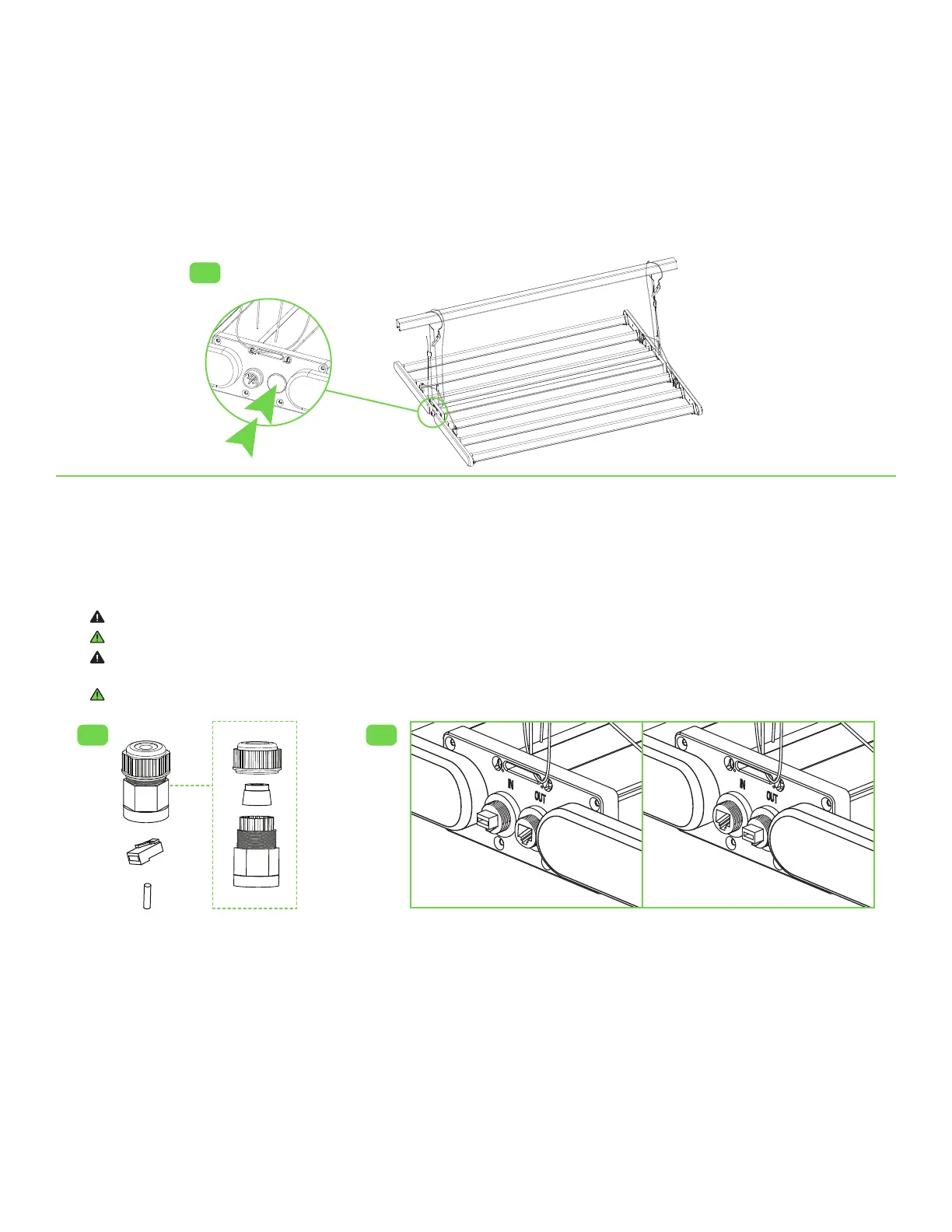
1. Scenario:ExternalcontrolsignalordummyplugisinsertedintheRJ45“IN”port(fig.6).
A.Externalcontrolsignalordummyplugoverridesthedigitaldimmingbutton.Theexternal
controllerordummyplugwillhavefullcontrolofthefixture.
B.TheRJ45“OUT”portisonlyactivatedwhenthereisanexternalcontrolsignalordummyplugconnectedtotheRJ45“IN”port.
C.Ifthismodeisutilized,upto1,000fixturescanbeoperatedifconnectedinseries.
Warning! DonotinsertanexternalcontrolsignalordummyplugintotheRJ45“OUT”port.TheLEDxturewillnotoperateinthismode(fig.7).
Attention!Seesection9tolearnhowtoconnectaGavitaMasterControllerGen2totheLEDxture.
Avertissement! Nepasinsérerunsignaldecommandeexterneoulafichesansrésistancedechargedansleport«EXTERNE»RJ45.
LedispositifàDELnefonctionnerapasenutilisantcemode(fig.7).
Avertissement!Consultezlasection9pourapprendrecommentbrancherleGavitaMasterControllerGen2audispositifàDEL.
8.3 MODE III: REMOVAL OF EXTERNAL CONTROL (Controller || Dummy Plug Failure)
1. Scenario:ExternalcontrollerordummyplugmalfunctionsorisremovedfromtheRJ45“IN”port.
A.TheLEDfixturewilldefaulttoOFF.Thiswillpreventthefixturefromaccidentallyturningonduetoawiringissueorsystemfailure.
B.TheLEDfixturecanbeturnedbackonbythedigitaldimmingbuttonwhenthereisnoexternalcontrol.
8.4 MODE IV: BREAKER || CONTACTOR PANEL CONTROL
1. Scenario:Customerutilizesabreakerorcontactorpanelforlinevoltageoperation.
A.DummyplugorexternalcontrolmustbeconnectedtoRJ45“IN”portonthefirstfixture.
B.IfthereisnoexternalcontrollerordummyplugconnectedtotheRJ45“IN”port,thentheLEDmustmanuallybeturnedonafter
poweringtheunit.
fig.5
fig.6 fig.7
✓ ✗

 Loading...