7
9. CONTROLLING WITH GAVITA MASTER CONTROLLER GEN 2:
Part No.:HGC906121
DESCRIPTION: Gavita
®
MasterControllerEL2-Gen2
I. RemovethecableglandassemblyontheLEDfixture.
II. RemovethedummyplugfromtheRJ45“IN”port.(Save for future use.)
III. Refertosection9.3forinstructionsonattachingthewatertightcableglandtotheinputcableonthefirstfixtureofthecontinuouschain.
IV. ForinstructionsonconnectingLEDfixturesinparallelorseries,refertosection9.1ondaisychainingwithinterconnectcables.
9.1 CONTROLLING UP TO 1,000 FIXTURES
I. RemovethedummyplugfromtheRJ45“IN”portonallLEDfixtures.
II. Usethecontrollercable(RJ45-RJ9)toconnecttheprimarychannelofthecontrollertotheRJ45“IN”portofthefirstLEDcontroller.
III. Usetheinterconnectcable(RJ45-RJ45)toconnecttheRJ45“OUT”portofthefirstLEDfixturetotheRJ45“IN”portofthesecondLEDfixture.
IV. Repeatthesestepstoconnectupto1,000LEDfixturesinseries.
Warning! PowercordandinterconnectcablesmustnottouchtheLEDrails.
Avertissement! Lecordond’alimentationetlescâblesdeliaisonnedoiventpastoucherauxtraversesdudispositifàDEL.
9.2 UTILIZING A 3RD PARTY CONTROLLER
*
I. Followthesamplestepsinsection8.3(Editor Note: EL2 Controller Section)
II.Forconfigurationofinterconnectcables,seesection9.4.(Editor Note: Custom Cables Section)
*This fixture is intended to be used with the Gavita e-Series controller platform. Compatibility with third party controllers is not guaranteed.
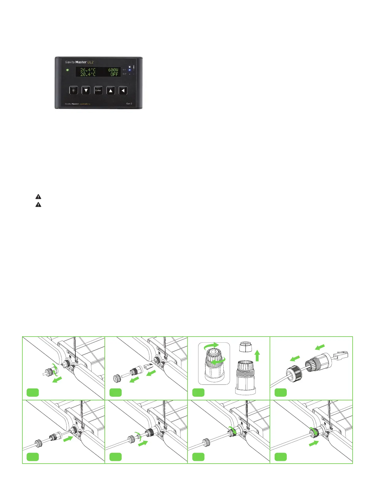
9.3 DAISY CHAINING - WATERTIGHT INTERCONNECTIONS
I. RemovetheprotectivecableglandfromtheRJ45“IN”port(fig.7).
II. RemovedummyplugfromRJ45“IN”port(fig.8).
III. Undotherearnutoftheprotectivecableglandandpullouttherubberseal(fig.9).
IV. Slidecablethroughthesecuringnutandtheglandcovering(fig.10).
V. PlugtheinterconnectcableintotheRJ45“IN”port(fig.11).
VI. Placetherubbersealonthewirebetweenthesecuringnutandglandcovering,thenpressintotheprotectivegland(fig.12).
VII. Tightenthesecuringnutontotheglandcovertocreateawatertightseal(fig.13-14).
VIII. RepeatstepsaboveforallIOportsinthedaisychain.
fig.7
fig.11
fig.8
fig.12
fig.10
fig.14
fig.9
fig.13