8
9.4 CUSTOM CONTROL CABLE AND 3RD-PARTY SPECIFICATIONS
The LED fixture can be used with most analog 0 -10 Volt DC communication systems.
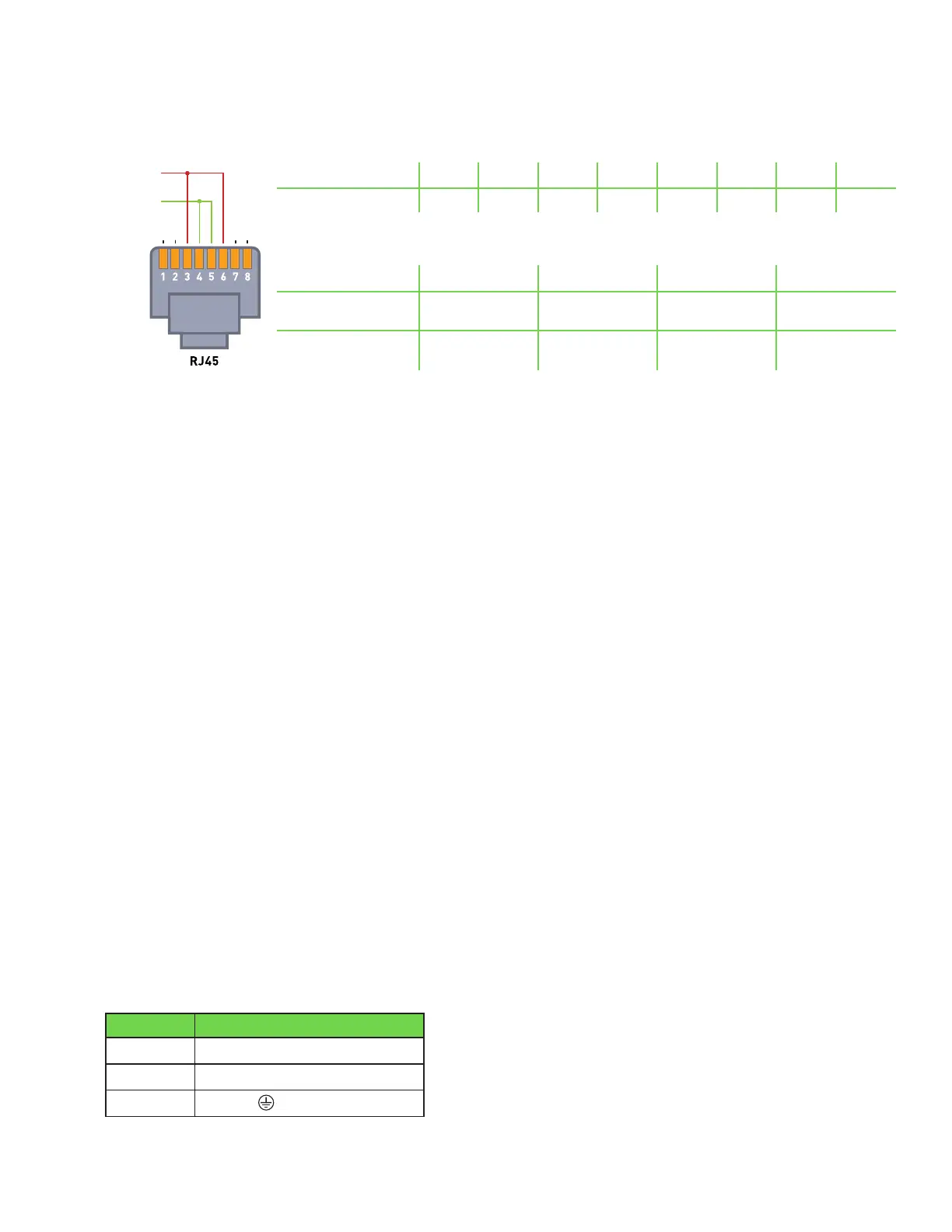
For analog control, please follow the chart below on custom wiring on the fixture side.
PIN OUT (FIXTURE SIDE RJ45 6P4C)
PIN 1 PIN 2 PIN 3 PIN 4 PIN 5 PIN 6 PIN 7 PIN 8
CONNECTION N/C N/C Signal GND GND Signal N/C N/C
DIMMING SEQUENCE
NC/Error State OFF ON CONTROL RANGE
RECOMMENDED
SIGNAL (VDC)
0.0 2.5 5.0 5.0V-10.0V
FIXTURE RESPONSE
(% Output of Fixture)
0% 0% 50% 50%-100%
9.5 CONTENTS OF THE REPEATER BUS CONNECTION KIT NOT INCLUDED. KIT SOLD SEPARATELY.
The e-Series adapter interconnect kit contains the following items:
HGC906712:1)1xGavitae-SeriesLEDAdapterInterconnectCable80ftKit
2)6xRJ45terminalconnectors
HGC906714:1)1xGavitae-SeriesLEDAdapterInterconnectCable80ftKit
2)3xRJ45+3xRJ14terminalconnectors
OPTIONAL: HGC906721:Gavitae-SeriesLEDAdapterInterconnectCable3WaySplitterRJ45
HGC906720:InterconnectCableCrimper
9.6 PREPARATION FOR USE WITH A CONTROLLER
Locatetheunstrippedinterconnectcable.
Cutthecabletothedesiredlengthandstripbothendsusingacrimptool(e.g.product#HGC906720,soldseparately).
InsertthecableendintotheRJconnectorsandusethecrimptooltofinishtheassembly.
9.7 CONNECTING THE LED FIXTURE TO THE MAINS
Make sure power cords:
1.Are notconcealedorextendedthroughawall,floor,ceiling,orotherpartsofthebuildingstructure.
2.Are notlocatedaboveasuspendedceilingordroppedceiling.
3.Are notpermanentlyaffixedtothebuildingstructure.
4.Areroutedsothattheyarenotsubjecttostrainandareprotectedfromphysicaldamage.
5.Arevisibleovertheirentirelength.
6.Areusedwithintheirratedampacityasdeterminedforthemaximumtemperatureoftheinstalledenvironmentspecifiedintheinstructions.
Ensurethecordisnotcoiledanddoesnottouchanyhotsurfaces.
Ifexternalswitchinggearisusedtoswitchthefixture,ensureitcancopewiththeinrushcurrentofthefixture.
Always use a double pole contactor suitable for switching a capacitive load.
Never use household timers to switch the fixture!
Switchoffmainpower.
Connectthepowercabletothemains.TheSunSystemRS1850LED120-240VpowercablesconnecttoaNEMAReceptacle.
TheSunSystemRS1850LED277Vusesanopen-endcable.
Cable Description Sun System RS 1850 LED 277 V
WIRE 277V
White Neutral (N)
Black Phase (L)
Green
Ground
( )
+Signal
(0-10V)
GND/VE
N/C
N/C
1 2 3 4 5 6 7 8
RJ45

 Loading...