Do you have a question about the SUNFORD ELECTRONICS APlusBoost Home MultiRoom SF001 and is the answer not in the manual?
Lists necessary tools and materials for installation, including ladder, drill, and power strip.
Place the indoor antenna for maximum signal boost, 1 foot from metallic objects and 3 feet from windows.
Mount the booster in a ventilated, dry, and heat-free location, ensuring it is not covered.
Discusses pole and wall mounting, emphasizing pole mounting for adjustability and placement 3 feet from windows, above the roof line.
Aim the outdoor antenna at the nearest cell tower; ensure minimum separation distances between indoor and outdoor antennas.
Connect the 3D-FB cable to the outside antenna and route it to the booster's 'OUTSIDE' port, finger-tightening connections.
Connect the inside antenna to the booster's 'INSIDE' port.
Plug the power supply into the booster and a power outlet, recommending a surge-protected power strip.
Explains how to check signal strength on iPhones using a dial code, as dBm is no longer displayed in Field Test Mode.
Guides users to check signal strength via phone settings or by downloading a third-party app like 'LTE Discovery'.
Describes the status lights for correct booster operation, including initial self-test and solid green indicators.
Explains blinking red and solid red lights indicating reduced gain or oscillation, and a power indicator being off.
Addresses blinking red lights (reduced gain) and solid red lights (shutoff due to oscillation).
Provides guidance for when the DC power indicator is off, suggesting checking the power supply or contacting support.
Explains the causes of oscillation and how to confirm and solve it by maintaining antenna separation.
Covers separation distances, device usage environment, RF safety warnings, and consumer device registration requirements.
Details model number, FCC ID, connectors, noise figure, impedance, weight, frequency bands, power output, and operating temperature.
Outlines the three-year warranty, conditions for claims, and exclusions like misuse or neglect.
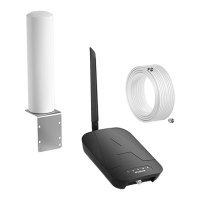
Provides details on components (antennas, cables), their product numbers, gain/loss figures, and notes on their use.
| Model Number | 001 |
|---|---|
| FCC | 001 |
| Frequency | 698-716MHz, 824-849MHz, 1850-1915MHz, 1710-1755MHz 728-745MHz, 869-894MHz, 1930-1995MHz, 2110-2155MHz |
| Power output for single cell phone (Uplink)dBm | 700A-MHz 8 00MHz 1900MHz 1700MHz Band12 Band5 Band2 Band4 62 65 65 65 |
| Power output for single cell phone (Downlink)dBm | 700A-MHz 8 00MHz 1900MHz 2100MHz Band12 Band5 Band2 Band4 64 65 68 68 |
| EIRP | 1W Max |
| Connectors | F-Female on the inside Antenna / F-Female on the Outside Antenna |
| Antenna lmpedance | 75 Ohms / 75 Ohms |
| Noise figure | 5 dB nominal |
| lsolation | >110 dB |
| Operating temperature | 5℉to 140℉(-15℃~60 ℃) |
| Power Requirements | AC / DC 12V, 1.5A, w/1.35X3.5mm Jack |
| Weight | 0.35Kg |
|---|