This document describes the APlusBoost Home MultiRoom Cell Phone Signal Booster, a device designed to improve cellular signal strength within a building.
Function Description:
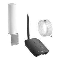
The APlusBoost Home MultiRoom Cell Phone Signal Booster is a system that amplifies existing cellular signals to provide better coverage indoors. It consists of an outdoor antenna, an indoor antenna, a booster unit, and connecting cables. The outdoor antenna captures weak cellular signals from the nearest cell tower, which are then sent to the booster. The booster amplifies these signals and transmits them to the indoor antenna, which broadcasts the stronger signal throughout the desired indoor area. This process also works in reverse, amplifying outgoing signals from your phone to the cell tower. The system is designed to provide a significant increase in signal strength, leading to improved call quality, faster data speeds, and more reliable cellular service.
Important Technical Specifications:
- Model Number: SF-002
- FCC ID: 2A34B-SFZN002
- Connectors: F-Female on the inside antenna / F-Female on the outside antenna
- Noise Figure: 5 dB nominal
- Antenna Impedance: 75 Ohms / 75 Ohms
- Weight: 0.35kg
- Frequency Bands:
- 698-716MHz, 776-787MHz, 824-849MHz, 1850-1915MHz, 1710-1755MHz (Uplink)
- 728-746MHz, 746-757MHz, 869-894MHz, 1930-1995MHz, 2110-2155MHz (Downlink)
- Power output for single cell phone (Uplink)dBm:
- 700A-MHz: Band12 (62), Band13 (62)
- 700V-MHz: Band12 (62), Band13 (62)
- 800MHz: Band5 (65)
- 1900MHz: Band2 (65)
- 1700MHz: Band4 (65)
- Power output for single cell phone (Downlink)dBm:
- 700A-MHz: Band12 (64)
- 700V-MHz: Band13 (65)
- 800MHz: Band5 (68)
- 1900MHz: Band2 (68)
- 2100MHz: Band4 (68)
- EIRP: 1W Max
- Operating Temperature: 5°F to 140°F (-15°C~60°C)
- Isolation: >110 dB
- Power Requirements: AC / DC 12V, 1.5A, w/1.35x3.5mm Jack
- Antenna Gain/Loss (dB):
- Outdoor Antenna (A-SF001): LTE-A (8dBi), LTE-V (8dBi), 800MH (9dBi), 1900MH (10dBi), 1700MHz/2100MHz (10dBi) - Log Periodic Antenna (Default)
- Outdoor Antenna (A-SF002): 3dBi, 3dBi, 3dBi, 5dBi, 5dBi/5dBi - Omni Directional Antenna
- Outdoor Cable (RG660Feet): 4dB, 4dB, 4.3dB, 6.5dB, 6.5dB/7dB - 60 feet
- Outdoor Cable (3D-FB60Feet): 4.5dB, 4.5dB, 5.4dB, 8dB, 8dB/9dB - 60 feet (Default)
- Outdoor Cable (3D-FB30Feet): 2.1dB, 2.1dB, 2.5dB, 3.6dB, 3.6dB/4.1dB - 30 feet
- Indoor Cable (3D-FB30Feet): 2.1dB, 2.1dB, 2.5dB, 3.6dB, 3.6dB/4.1dB - 30 feet
- Indoor Cable (RG630Feet): 1.8dB, 1.8dB, 1.9dB, 3.1dB, 3.1dB/3.2dB - 30 feet
- Indoor Antenna (A-SF003): 8dBi, 8dBi, 8dBi, 10dBi, 10dBi/10dBi - Panel Antenna
- Indoor Antenna (A-SF004): 2dBi, 2dBi, 2dBi, 3dBi, 3dBi/3dBi - Whip Antenna (Default)
- Minimum Required Separation Distance Between Indoor and Outdoor Antennas:
- Straight line distance over 40 feet (12 meters)
- 30 feet (9 meters) horizontal distance
- 20 feet (6 meters) vertical distance (as far as possible)
Usage Features:
- Installation Process: The installation involves four main steps:
- Inside Antenna Placement: Place the indoor antenna in a location where the greatest signal boost is needed, at least 1 foot away from other metallic objects and 3 feet away from any windows. The booster should be placed in a well-ventilated area and not covered.
- Mount & Point Outside Antenna Toward Nearest Cell Tower: Mount the outdoor antenna using the included pole mounting or wall mounting options. It should be at least 3 feet away from any windows and installed over the roof line. The antenna must be pointed towards the nearest cell tower for optimal performance. Using an app like 'Open Signal' is recommended to find the nearest tower.
- Route & Connect Outside Antenna To Booster: Connect the white 3D-FB Cable to the outdoor antenna and route it into the home, securing the cable near the antenna. All connections should be finger tightened. Then, connect the cable to the 'OUTSIDE' port on the booster.
- Route & Connect Inside Antenna To Booster: Connect the indoor antenna to the 'INSIDE' port on the booster.
- Power Up The Booster & Optimize The System: Plug the power supply into the booster and then into the nearest power outlet. A power strip with surge protection is strongly recommended.
- Signal Strength Measurement: The manual provides instructions on how to measure signal strength on both iPhone and Android devices.
- iPhone®: Dial 3001#12345# then press call to access 'Field Test Mode' and view the decibel (dBm) reading.
- Android™: Navigate to Settings > About Phone > Status or Network > Signal Strength or Network Type and Strength. Downloading a third-party app like APP-LTE Discovery is also suggested.
- Light Patterns for Status Indication: The booster features band indicator lights on the front panel to show the status of each band.
- Correct Functioning: Lights turn green for about 1 second, indicating the booster has passed self-test and is in good condition. If there is no problem with the system, all indicators remain solid green during operation.
- Blinking Red: Indicates reduced gain. This happens when booster bands have reduced power due to a feedback loop condition called oscillation. This is a built-in safety feature to prevent harmful interference with a nearby cell tower. If the desired signal boost is not experienced, further adjustments are necessary.
- Solid Red: Indicates that a feedback loop condition caused oscillation and the band has shut off. This is a built-in safety feature that causes a band to shut off to prevent harmful interference with a nearby cell tower.
- Warranty: The booster is covered under a three-year product warranty for failures or defects resulting from craftsmanship and/or materials. Dated proof of purchase is required for warranty claims. Contact the retailer/reseller directly for warranty issues. If the reseller is no longer available, contact the manufacturer. Unavailability of the product may result in a refund or a return authorization letter. Refurbished products may be used for product replacements.
Maintenance Features:
- Troubleshooting: The manual provides solutions for common issues:
- Fixing Blinking Red Lights:
- Band Indicator Lights Blink 1 To 15 Times (1 cycle): This means the gain is lowered 1-15 dB. If coverage is good and reception is good, you can ignore the blink.
- Band Indicator Lights Blink All The Time: This means the gain is lowered 15-25 dB. Check and install the whole system again.
- Fixing Solid Orange Lights: This means the band has shut down. Check and install the whole system again.
- All Indicator Lights Are Not On: Verify the power supply has power. Contact customer support for replacement if needed.
- How does oscillation happen?
- Indoor antenna receives leak signal from the outdoor antenna.
- Booster amplifies the signal and then transmits it to the outdoor antenna.
- Outdoor antenna broadcasts the signal in the air, some of the signal back to indoor antenna and become leak signal.
- If the gain of the booster is higher than the loss of the leak signal, the leak signal will become bigger and bigger, finally oscillation happened.
- How to confirm that oscillation has occurred?
- Panel light flash or solid red/orange after power on.
- Screw off the indoor antenna from the booster.
- Restart the power supply.
- All indicator lights flash once time after power on show self-test finished.
- How to solve the problem of oscillation: Keep enough distance between indoor and outdoor antennas, adhering to the minimum separation distances specified in the technical specifications.
- Booster Placement: The booster unit may become about 30 degrees Fahrenheit higher than the ambient temperature, which is a normal phenomenon. Ensure it is placed in a well-ventilated area.
- FCC Compliance: The device complies with Part 15 of FCC rules. Operation is subject to two conditions: (1) This device may not cause harmful interference, and (2) this device must accept any interference received, including interference that may cause undesired operation. Changes or modifications not expressly approved by APlusBoost could void the authority to operate this equipment. The device must be installed to comply with the 10 meter above ground maximum antenna height limitation OR the device has a 10 meter above ground maximum antenna height limitation when the device is used with a handset that covers the 1710-1755 MHz band and that owners could be subject to potential FCC enforcement action for noncompliance.
- RF Safety Warning: Any antenna used with this device must be located at least 8 inches from all persons.
- Consumer Device: This is a CONSUMER device. Users MUST REGISTER THIS DEVICE with their wireless provider and have their provider's consent. Most wireless providers consent to the use of signal boosters. Some providers may not consent to the use of this device on their network. If you are unsure, contact your provider. In Canada, users MUST meet all requirements set out in ISED CPC-2-1-05. Users MUST operate this device with approved antennas and cables as specified by the manufacturer. Antennas MUST be installed at least 20 cm (8 inches) from any person. Users MUST cease operating this device immediately if requested by the FCC (or ISED in Canada) or a licensed wireless service provider. WARNING: E911 location information may not be provided or may be inaccurate for calls served by using this device. This device may be operated ONLY in a fixed location for in-building use.