26
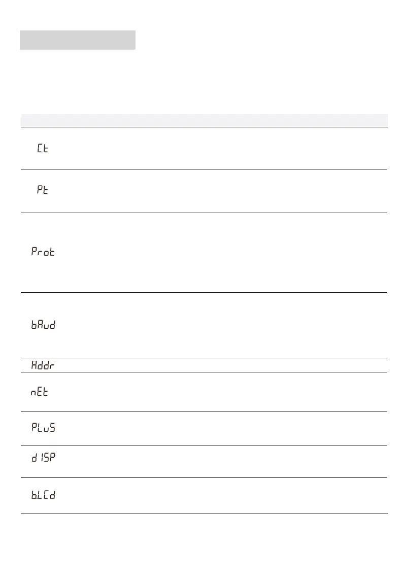
The parameters of the meter equipped only with 100A/0.333VCT have been set before delivery, and
can be installed directly after acceptance, without setting the parameters again, and the meters
equipped with the rest of the CT and Rogwski coils need to set their parameters before installation.
Programming function
Programming Parameter
Parameter Value range Description
Voltage ratio, used for setting the voltage ratio of the input loop.
When the voltage is connected to the line via the transformer, Pt= the rated
voltage of the primary loop / the rated voltage of the secondary circuit.
When the voltage is directly connected to the line, Pt shall be set as 1.0.
1: 645
2: n.2
3: n.1
4: E.1
5: O.1
Settings for communication stop bit and Parity: bits
1: 645mode
2: None parity, 2 stop bits, n.2
3: None parity, 1 stop bit, n.1
4: Even parity, 1 stop bit, E.1
5: Odd parity, 1 stop bit, O.1
0: 1.200
1: 2.400
2: 4.800
3: 9.600
Communication baud rate:
0: 1.200 bps
1: 2.400 bps
2: 4.800 bps
3: 9.600 bps
1 ~ 254 Communication address
0: n.34
1: n.33
Option for wiring mode:
0: n.34 represents three phase four wire
1: n.33 represents three phase three wire
0: P0
1: P1
Pulse output:
0 ~ 30
0: Timely display
1 ~ 30: Time interval of actual display
0 ~ 30
Backlight lighting time control(minute)
0: Normally light
1 ~ 30: Backlight lighting time without button operation
1 ~ 8
0.1 ~ 1.0
1:CT01:100A/333mV 2:CT02:250A/333mV
3:CT03:400A/333mV 4:CT04:500A/333mV
5:RS01:1000A/333mV 6:RS02:2000A/333mV
7:RS03:3000A/333mV 8:RS04:4000A/333mV
P0: First channel actsive energy pulse
P1: Second channel actsive energy pulse


 To Next Page