5 Electrical Installation User Manual
34
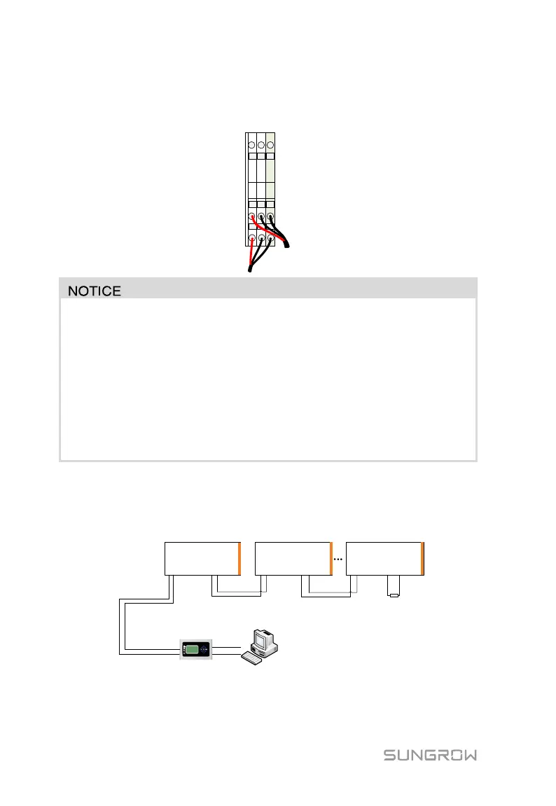
Step 7 Follow the same steps to connect the output cables to the A2, B2 and FG,
to finish the communication connection.
Communication cable must be shielded twisted pair cable. Communication
unstable or communication failure may follow if otherwise.
Communication cable should be far away from the high voltage cable. Place
the communication cables and power cables in parallel or strap them
together is strictly forbidden. Communication interface or device damage if
otherwise. If not prevented, lead the communication cable through
galvanized tube for shielding.
Communication Solution
The communication method of PVS is shown below:
PVS 1
A1 B1 A2 B2
RS485A
RS485B
PC
PVS 2
A1 B1 A2 B2
PVS n
A1 B1 A2 B2
(optional)
120Ω resistor
Logger
Connect A1 and B1 of the first PVS to A1 and B1 of data collector;
Connect A2 and B2 of the first PVS to A1 and B1 of the second PVS;
 Loading...