User Manual 5 Electrical Installation
33
5.4.4 Communication Connections
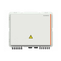
Refer to the figure below for communication terminals inside the PVS.
Upper terminal connects to input and lower terminal connects to
output. User may adjust according to real need.
Step 1 Unscrew the gland terminals "MONITOR INPUT", "MONITOR
OUTPUT".
Step 2 Pull the communication cable inside the PVS through the gland
terminals.
Step 3 Strip off the cables’ protection layer and the insulation layer until the
copper core is 8mm outside.
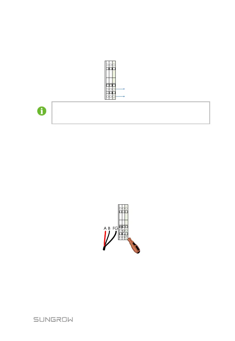
Step 4 Insert the screwdriver inside the input cable terminal holes. Pull the
screwdriver until the leaf spring is bounced completely.
Step 5 Insert wires into bottom of wiring holes A1, B1, and FG. Among them:
− Connect communication cable RS485-A to A1;
− Connect communication cable RS485-B to B1;
− Connect communication cable shielding layer to terminal FG.
Step 6 Loosen the screwdriver to let the leaf spring connect to the cable.
 Loading...