SUNPOWERCORPORATION
SafetyandInstallationInstructions‐Document001‐14158RevAI
©2021SunPowerCorporation.Allrightsreserved.Specificationsincludedintheseinstructionsaresubjecttochangewithoutnotice.Page|5
Table2:ModuleGroundingKey
ModuleModelGroundingKey
2
SunPowerA‐Series,M‐Series,P ‐Series,E‐Series,
X‐Series,MAX2,MAX3andNEmoduleshaveno
groundingrestrictions:
Legacymodulesmustbe
positivelygrounded:
Allmodelnumbers
startingwith“SPR‐AZZZ”,
“SPR‐AZZZ‐BLK”,“SPR‐
MZZZ”,“SPR‐MZZZ‐BLK”,
“SPR‐PYY,SPR‐PY‐XXX‐
UPP”,“SPR‐EYY”,“SPR‐
XYY”,“SPR‐MAX2”,or
“SPR‐MAX3”.
SPR‐ZZZNE‐BLK‐D
SPR‐ZZZNE‐WHT‐D
SPR‐ZZZE‐WHT‐D
SPR‐ZZZ‐WHT‐D
SPR‐ZZZE‐BLK‐D
SPR
‐ZZZ‐BLK‐D
IMPORTANT!Foroptimalperformance,SunPowermoduleslistedabove
asneedingpositivegroundingmustbeconfiguredasdescribed.Failureto
complywiththisrequirementwillreducesystemperformanceand
invalidateSunPower’sLimitedPowerWarrantyforPVModules.
4.3NEC2017690.12Compliance
Modulescontaining‐MLSDintheproductnamecomewithapre‐installed
SunSpeccompliantrapidshutdownreceiverfromTigoEnergyIncthat,whenused
andinstalledwithapprovedequipment,constituteaUL1741listedarraymeeting
therequirementsofNFPA70,2017article690.12(B)(2).PleaserefertoTigo
Energy’slistof
approvedequipmentforadditionaldetailsandrequirements.
5.0 ModuleMounting
TheSunPowerLimitedWarrantyforPVModulesiscontingentuponmodules
beingmountedinaccordancewiththerequirementsdescribedinthissection.
5.1SiteConsiderations
SunPowermodulesshouldonlybemountedinlocationsthatmeetthefollowing
requirements:
OperatingTemperature:AllSunPowermodulesmustonlybemountedin
environmentsthatensuretheywilloperatewithinthefollowingtemperatures:
OperatingTemperaturerange
‐40°Cto+85°C
‐40°Fto+185°F
OperatingTemperaturerange(w/MLSD)
‐40°Cto+75°C
‐40°Fto+167°F
Careshouldbetakentoprovideventilationbehindorunderneaththemodules,
especiallyinhotenvironments.
Shading:Modulesshouldbeinstalledsothatpermanentshadingofcellsis
avoidedandpartialshadingthatmayoccurduringcertaintimesofthedayor
yearisminimized.Permanentshadingisdefinedasshadethatiscastoverthe
sameposition(ofconstantarea)ofthesolarmodulethroughout thegeneration
hoursoftheday.
Shadingmayinduceincertaincasesstrong
energyproductionreduction,evenin
caseofsmallshadingandshouldbeavoidasmuchaspossible,speciallyatmid‐
daywhentheproductionismaximum.
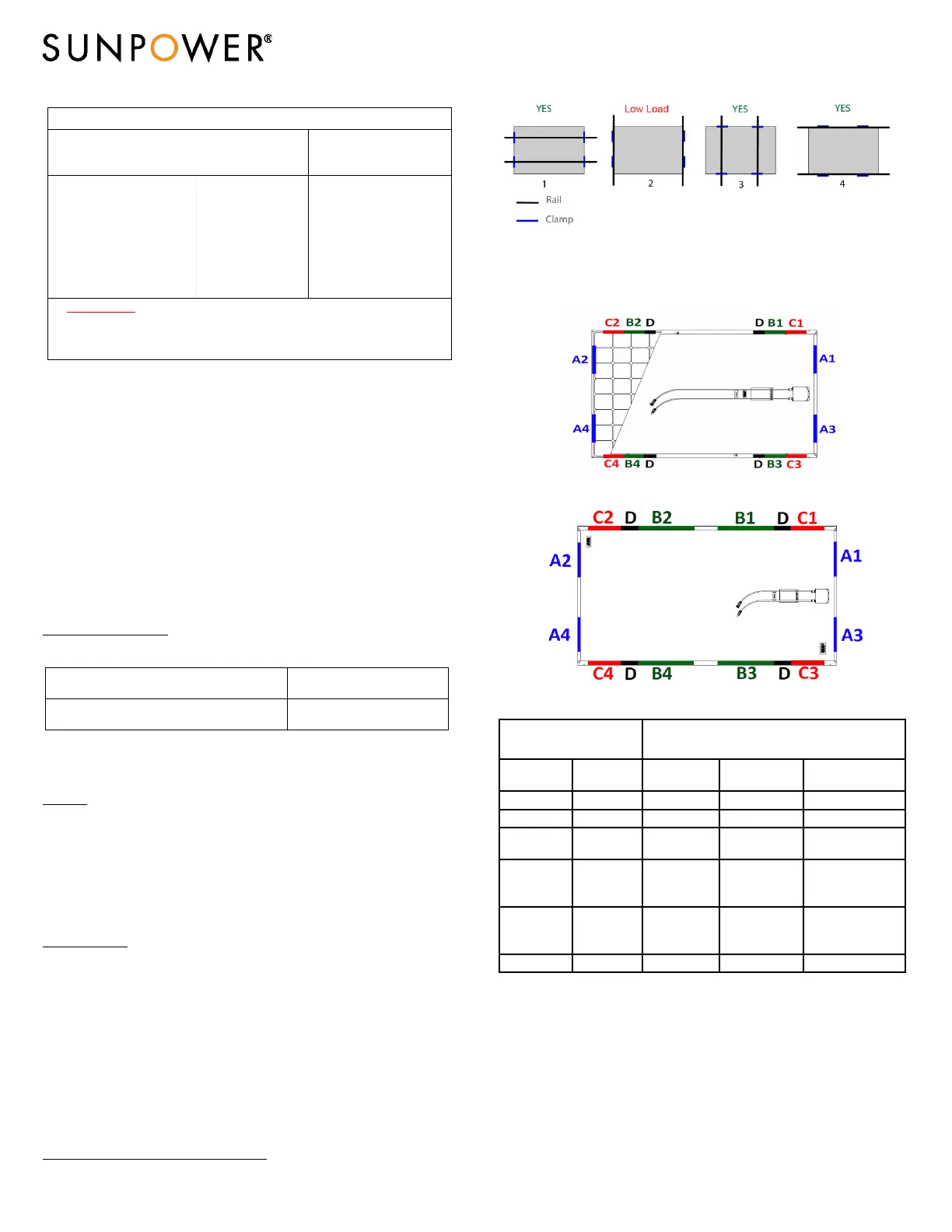
DesignStrength:SunPowermodulesaredesignedtomeetamaximumpositive
(orup/down,e.g.wind)andnegative(ordownward,e.g.staticorsnowload)
designpressuredescribedintheTable3.Moduleshavealsobeenevaluatedby
ULforamaximumnegativeorpositivedesignloadof30psf.P19moduleshave
beenevaluatedbyULforamaximumnegativedesignload
of75psfand
maximumpositivedesignloadof125psf.M‐Seriesmodulewerenotevalua ted
byULforEndMount.
Figure1:MountinglocationsforSunPowerModulesshowswheretomountto
themoduleframe.Table3definesmountingoptions,attachmentlocationsand
resultingloadratingachievedfor
eachmoduleconfiguration.
2
YYisanumberrangingfrom15to22andZZZispanelwattage.
Configurations1and3showmountingwithrailsupport,2and4showmounting
withoutrailsupport.
For96cells,A‐Series,M‐Seriesand104c:
For128cellsandP‐Series:
Table3:MountingConfigurationsandLoadResistance
ModuleConfiguration
Mountingzonedistancefromcornerin
(mm)
1
Modulesize Frametype
A
(1&2&3&4)
B
(1&2&3&4)
C
(1&2&3&4)
96cell G3 50‐350 150‐620
D
50‐150
96cell G5 50‐400 300‐400 50‐300
128cell&P‐
Series
G4.x 50‐350 375‐880
D
50‐375
A‐Series&
M‐Series72
cell
G4.2/5.1/
5.6
50‐350 296‐536 50‐296,536‐796
A‐Series&
M‐Series66
cell
G5.2 50‐350 300‐500 50‐265,514‐714
104cells G4.2 50‐350 150‐380 50‐150
D
–Thereisa20mmzoneat388‐408mmfromthecornerwheremountingisnotalloweddue
tothemodulestackingpinfeature.Applicableonlyto96‐cellcommercialand128‐cell.
1)Nopartofthemoduleclampmayextendbeyondthisarea.