SUNPOWERCORPORATION
SafetyandInstallationInstructions‐Document001‐14158RevAI
©2021SunPowerCorporation.Allrightsreserved.Specificationsincludedintheseinstructionsaresubjecttochangewithoutnotice.Page|4
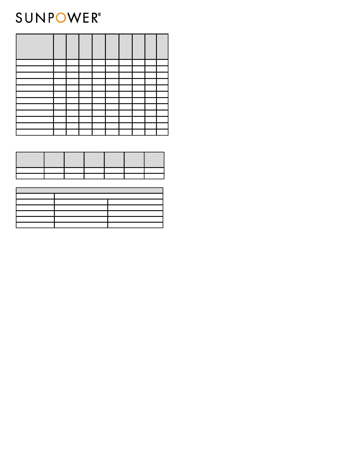
Module
Rated
Power
(W)
+5/‐0%
Voltage
atRated
Power
Vmpp
(V)
Current
atRated
Power,
Impp(A)
Open
Circuit
Voltage
Voc(V)
+/‐3%
Short
Circuit
Current,
Isc(A)
+/‐3%
Current
Temp.
Coeff.
%/°C
Voltage
Temp.
Coeff.
%/°C
Power
Temp.
Coeff.
%/°C
System
Safety
Class
SPR‐M480‐COM 480 44.2 10.87 52.6 11.58 0.060 ‐0.239 ‐0.30 II
SPR‐M475‐COM 475 43.9 10.82 52.6 11.57 0.060 ‐0.239 ‐0.30 II
SPR‐M470‐COM 470 43.7 10.76 52.5 11.56 0.060
‐0.239 ‐0.30 II
SPR‐M465‐COM 465 43.5 10.70 52.5 11.55 0.060 ‐0.239 ‐0.30 II
SPR‐M460‐COM 460 43.2 10.64 52.5 11.54 0.060 ‐0.239 ‐0.30 II
SPR‐M450‐COM 450 42.8 10.52 52.4 11.51 0.060 ‐0.239 ‐0.30 II
SPR‐M480‐COM‐MLSD 480 44.2 10.87 52.6 11.58 0.060 ‐0.239 ‐0.30 II
SPR‐M475‐COM‐MLSD 475 43.9 10.82 52.6 11.57 0.060 ‐0.239 ‐0.30 II
SPR‐M470‐COM‐MLSD 470 43.7 10.76 52.5 11.56 0.060 ‐0.239 ‐0.30 II
SPR‐M465‐COM‐MLSD 465 43.5 10.70 52.5 11.55 0.060 ‐0.239 ‐0.30 II
SPR‐M460‐COM‐MLSD 460 43.2 10.64 52.5 11.54 0.060 ‐0.239 ‐0.30 II
SPR‐M450‐COM‐MLSD 450 42.8 10.52 52.4 1.51 0.060 ‐0.239 ‐0.30 II
P5 UPP
Module
RatedPower
(W)
Voltageat
RatedPower
Vmpp(V)
Currentat
RatedPower,
Impp(A)
OpenCircuit
VoltageVoc
(V)
ShortCircuit
Current,Isc(A)
Maximum
SystemVoltage
ULVmax(V)
SPR‐P5‐525‐UPP 525 38.3 13.71 46.8 14.77 1500
SPR‐P5‐520‐UPP 520 38.0 13.69 46.6 14.76 1500
Bifaciality(φPmax) 70%+/‐10%
PmaxBiF05
551W 546W
IscBiF05
15.51A 15.50A
PmaxBiF10
578W 572W
IscBiF10
16.25A 16.24A
PmaxBiF20
630W 624W
BifacialCharacteristics
4.0 ElectricalConnectionsandSystemMonitoring
Modulesmaybeconnectedinseriesorparalleltoachievethedesiredelectrical
outputprovidedcertainconditionsaremet.
Evenifallowedbylocalregulation,PlugandSocketconnectorsmatedtogetherin
aPVsystemmustbeofthesametype(model,rating)fromthesame
manufactureri.e.aplugconnector
fromonemanufacturerandasocket
connectorfromanothermanufacturer,orviceversa,shallnotbeusedtomakea
connection.
SunPowerrecommendsaconservativeminimumbendingradius(R)5xcable
diametermustbemaintainedandmustnotbebentonthedirectexitofthe
connectororjunctionbox.
Avoidexposureofelectricalconnectionstodirect
sunlightanddonotplacetheconnectorinalocationwherewatercouldeasily
accumulate.Installersmustrefertoconnectormanufacturer’sinstructionfor
furtherinstallationandconnectionrequirements.
Connectorsarefactoryassembledwithintentionalgapsbetweenthe cabl enut
andthebodyofthe
connector.Donotretightenmoduleconnectornutsasthis
mayleadtostresscrackingoftheconnectorassemblyandwillvoidthewarranty.
4.1EquipmentGrounding
Toreducethepossibilityofelectricalshock,groundtheframeofthemoduleor
arrayperNECbeforewiringthecircuit.Inordertoinstallinaccordancewiththeir
ULListing,SunPowermodulesmustbegroundedusinggroundinghardwarethat
meetsrequirementsforgroundingsystemsinUL467,UL1703,or
UL1741;on
anodizedaluminumframes.SunPowerrecommendsusingoneofthefollowing
methodsofgroundingthemoduleframe.Inaddition,toavoidcorrosiondueto
theuseofdissimilarmetalsSunPowerrecommendsstainlesssteelbetween
copperandaluminum.FortheGeneration5(G5)frame,onlymethods1and2
apply.A‐Series‐BLKmodulesmustbeinstalledwiththeGroundLugAssemblyof
theInvisimountmountingsystemusingtheIlscoGBL‐4DBTgroundinglug
tightenedtoatorqueof85in‐lbstobondthemoduleframetotherail.Therails
usedforbondingmustbepartofthe
system’sgroundpath.
1)Attachalay‐inlug(IlscoGBL‐4DBT,BurndyCL50‐DB‐TorTycoSolklip1954381‐
2)tooneofthegroundingholesonthemoduleframe,andattachthe
groundconductortothelug.Usestainlesssteelhardware(bolt,washers,
andnut).Useanexternal‐
toothstarwasherbetweenthelugandthe
moduleframeinordertopiercetheanodizingandestablishelectrical
contactwiththealuminumframe.Theassemblymustendwithanutthat’s
torquedto20–25in‐lb(fora#10‐32bolt).Alockwasherorotherlocking
mechanismisrequired
tomaintaintensionbetweentheboltandthe
assembly.Theconductormustbeattachedtothegroundlugusingthelug’s
setscrew.RefertoNEC690.
2)SunPowermodulesmayalsobegroundedthroughtheuseofSunPowerIFF
clipswhichareULListed(1703and1741).IFFclip
torquevalueis35–45in‐
lbsfora1/4‐20orM6bolt,butmaybehigherinspecificapplications.
WhenusingIFFclips,themodulemountingsystemmustbegroundedas
perNEC250.
Note:Method3isevaluatedtoUL1703byETL.Assuch,theuseofthese
devices
isnotconsideredpartoftheULListingofthesemodules.
3)IftheUniracSOLARMOUNTsystem isusedformountingthemodules,
groundingisachievedusingeitheraBURNDYWileyWEEB‐UMCorWEEB‐
UGC‐1groundingclipincombinationwithUnirac’sMidorEndclampsand
1/4‐
20boltandflangednut,torquedto120in‐lbs.IftheSOLARMOUNT‐I
systemisusedgroundingisachievedwiththeUniracUGC‐2groundingclips
incombinationwithUnirac’sMidorEndclampsandSliderswitha1/4‐20
boltandflangednuttorquedto120in‐lbs
Note:
Method4wasevaluatedtoUL2703byTUV.Assuch,theuseofthese
devicesisnotconsideredpartoftheULListingofthesemodules.
4)SunPowermodulesmayalsobegroundedusingaWEEB‐9.5NLgroundclipin
betweenthemoduleandsupportingstructure.Thiscombinationis
secured
witha1/4″stainlesssteelrivetora1/4‐20by3/4″zinc‐platedboltwith
zinc‐platedK‐nuttorquedtomin.6ft‐lbstosecurethemoduletominimum
12ga.G90coatedsteelorZ‐purlin,eitherpaintedorunpainted.TheWEEB‐
9.5NLisforsingle
useonly.
5)Othergroundingmethodsmaybeusedinconjunctionwithamodulemounting
systemtestedtoUL2703.Fortheseinstallations,theSunPowermoduleand
framestylemustbetestedandpartoftheinstructionsforthelisted
mountingproduct.TheSunPowermodulemustbeinstalledinaccordance
with
theseinstructionsaswellasthemountingsystem’slistedinstructions.
6)SunPowerG5‐framemodulesmaybegroundedthroughtheuseofan
InvisiMountmidclampthatbondsthemoduleframetotheInvisiMount
rail.InvisiMountrailsectionsmustbebondedandconnectedtoa
groundingconductorusingmethodsandmaterials
specifiedinthe
InvisiMountmanual.
Whenusingmethods2,3,4,5or6themodulemountingstructuremustbe
groundedasperNEC250.Toensuresystemsafetyandstructuralintegrity,strict
adherencetoapplication‐specificSunPowerdocumentationisrequired.
4.2SystemGrounding
ReviewTable2belowforthepropergrounding techniquesfortheinstallationof
yourparticularSunPowermodules.
4.3SeriesConnection
Themodulesmaybewiredinseriestoproducethedesiredvoltageoutput.Do
notexceedthemaximumsystemvoltageshowninmoduledatasheetsand
productlabel.
4.4ParallelConnection
Themodulesmaybecombinedinparalleltoproducethedesiredcurrentoutput.
Eachseriesstringormodulemayberequiredtobefusedpriortocombiningwith
otherstringsiftheresultingmaximumfusesizeallowed(numberofmodules
whichcanbeconnectedinparallelandprotectedbyonefuse)
exceedsthefuse
ratingasshowninthemoduledatasheetandproductlabel.Pleaserefertothe
NECArticle690foradditionalfusingrequirements.
 Loading...