SUNPOWERCORPORATION
SafetyandInstallationInstructions‐Document001‐14158RevAI
©2021SunPowerCorporation.Allrightsreserved.Specificationsincludedintheseinstructionsaresubjecttochangewithoutnotice.Page|7
5.2MountingConfigurations
Modulesintegratedintoormountedoveraroofingsystemmustbemounted
overafire‐resistantroofcoveringratedfortheapplication.Modulesmaybe
mountedatanyangle,fromhorizontaltovertical.Toreducesoiling,modules
shouldbemountedataminimumof10degrees.
Residential(black)moduleframeshave
twoprofiletypes,G3andG5.Commercial
(silver)moduleframeshavepermanentlyattachedstackingpins.Mounting
systemhardwareusedwithcommercialmodulesmustaccountforthepresence
ofthesestackingpins.MechanicalspecificationsformodulesareshowninTable
4.
Inordertopreventwaterfromenteringthejunction
box,whichcouldpresenta
safetyhazard,modulesshouldbeorientedwiththejunctionboxinthe
uppermostpositionandnotbemountedsuchthatthecellfacesdownward(e.g.
onatrackingstructurethatpositionsthemoduleswiththejunctionboxfacing
skywardduringsleepmode).
For128‐celland
P‐Seriesmodulesaminimumof4″ofclearancebetweenthe
moduleframesandthestructure(orgrade)isrequired;forallothermodulesa
minimumof1.5″ofclearanceisrequired.Therequiredminimumclearance
betweeninstalledmodulesis1/4″.
ThemoduleisonlyULListedforuse
whenitsfactoryframeisfullyintact.Donot
removeoralterthemoduleframe,anddonotcreateadditionalmountingholes
becausedoingsomaycompromisetheintegrityoftheframe.
Modulesmaybemountedusingthefollowingmethodsonly:
1) FrameHoles:Securethemoduletothestructureusing
thefactory
mountingholes.Four1/4″stainlesssteelbolts,withnuts,washers,andlock
washersarerecommendedpermodule;tightenedtoamin.torqueof10in‐
lb.RefertoTable4forthemoduledimensionsandholelocations.This
methodhasbeencertifiedbyathird‐partyorganizationaccording
toUL
1703.Forframeholemounting,modulesmustbesecuredusingtheholes
locatedat322mmfromtheshortendofthemodule(96‐cellmodules);and
433mmfromtheendofthemodule(128‐cellmodules).Forcarport
installationsthesupportingstructurehasbeenpre‐drilled.For128‐cell
modulesforcarportassembly,modulesmustbesecuredusingonlythe
holeslocated433mmfromtheendsofthemoduleandhardwaredescribed
aboveinSection4.1,Item5.SeeFigure2forcarportassemblydetails.
2) ClampsorClips:MountthemodulewiththeIFFclipsonthe
longersidesof
themodule.Thecenterlineoftheclipsmustbe50‐400mmforG5frame
(150–380mmforG3frame)fromthecornerofthemodule.Ensurethatthe
clampsareofsufficientstrengthtoallowforthemaximumdesignpressure
ofthemodule.TheIFFcliphardwaremustbe
tightenedtoatorqueof35‐45
in‐lbs.Clampsthatsecuretothe
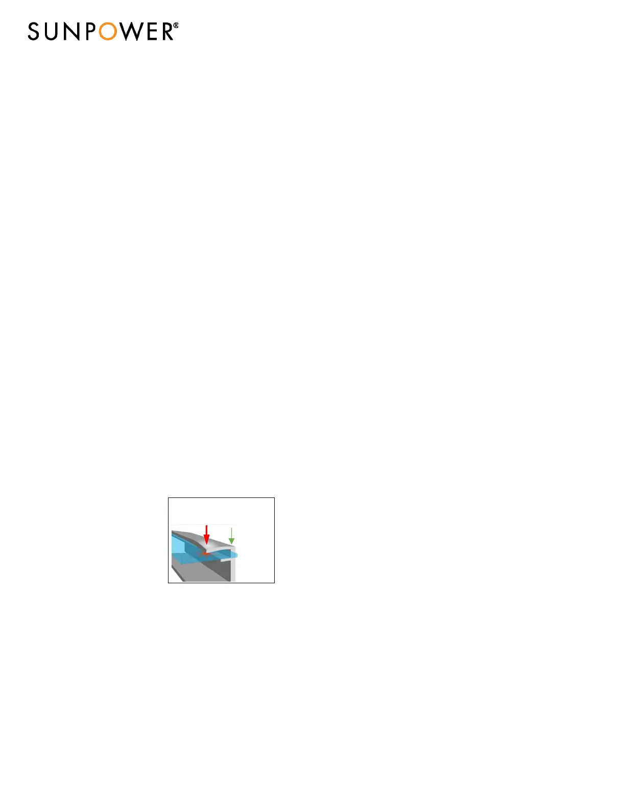
topoftheframemustnot
deformthetopflange.Clamps
mustapplyforcecollinearwith
the‘wall’ofthemoduleframe
andnotonlytothetopflange.
Clampsorinstallationprocedures
thatputexcessive
forceonthe
topflangewilldeformtheframe,
voidthemodulewarrantyand
riskglassbreakage.Figure1a
illustrateslocationsfortopframeclampforce.Donotclampwithin50mm
ofmodulecornerstoreduceriskofframecornerdeflectionandglass
breakage.Whenclampingtothemoduleframe,torque
shouldnever
exceed132in‐lbs(15Nm)toreducechancesofframedeformationand/or
glassbreakage.Iftheclampmanufacturerrecommendsaspecifictorque
valuewhichislowerthan132in‐lbs(15Nm),theinstallershouldusethe
clampmanufacturer’storquevalue.Iftheclampmanufacturerrecommends
a
specifictorquevaluewhichishigherthan132in‐lbs(15Nm),theinstaller
shouldcontacttheclampmanufacturerforacceptanceofthe132in‐lbs(15
Nm)maximumtorquevalueortofindalternativeclamps.Mounting
systemsshouldbeevaluatedforcompatibilitybytheprojectownerbefore
installing.
3) End
Mount:Endmountingistheattachmentoftheshortersideofthe
moduleframetoasupportingrailusingIFFclipstightenedtoatorqueof
35‐45in‐lbs.Thecenterlineoftheclipsmustbe50‐400mmfromthecorner
ofthemodule.Theend‐mountingrailand
clipsorclampsmustbeof
sufficientstrengthtoallowforthemaximumdesignpressureofthe
module.Verifythiscapacitybeforeinstallation.
4) Helix™MountingSystem:SeeUL2703Helixsysteminstallationmanualfor
details.
5) SunPower‐specifiedorSunPower‐suppliedmountingsystems:Mount
moduleswithstrictadherencetoSunPower
documentation,using
hardwaresystemssuppliedbyorspecifiedbySunPower.
5.3BifacialGain
Variousenvironmentalandinstallationparametersaffectbifacialgain.Albedoisa
measureoftheamountoflightreflectedfromthegroundsurface.Ahigher
albedofactorwillincreaseirradianceonthebacksideandresultinhigherbifacial
gainofthemodule.Thesurfaceconditions,monthoftheyear,timeofday,
GHI
andDNIbothinfluencetheamountofincidentrearsideirradiance.
SunPowerrecommendstocheckwithsolarmodulemountinghardwaresupplier
inordertodeterminetheStructureShadingfactorofyourparticularinstallation.
TheStructureShadingFactorvarieswithrackingsystemdesign,irradiance,
albedoandheightofmoduleinstallationabove
groundandhasanoverallimpact
ontherearsideirradiancemismatch.
TheRearsidemismatchlossesareproportionaltothealbedo,heightofthe
modulesabovegroundandstructureshadingfactor.Theirradiancenon‐
uniformityontherearsideresultsinmismatchgenerallyasthealbedoincreases
andinstallationheightof
themodulesarelowertotheground.
5.4BifacialElectricalConsiderations
Theoverallelectricalbifacialgainisdeterminedbythecombinationofalbedo,
irradiance,shadinglossesfromtherearside,rearsidemismatchandheightof
installationaboveground.PleaserefertotheSunPowerdatasheetforthe
electricaloutputswithrespecttotheoverallbifacialgain.Pleaseutiliseasuitable
performancesoftwarepackageto
simulatetheoverallbifacialgain
5.5ModuleHandling
Donotplacemodulesfaceforwardindirectcontactwithabrasivesurfaceslike
roofs,driveways,woodenpallets,railings,stuccowalls,etc…
Themodulefrontsurfaceglassissensitivetooilsandabrasivesurfaces,which
mayleadtoscratchesandirregularsoiling.
Duringstorage,modulesneedtobeprotectedfromrainor
anykindsofliquids.
Requiredstoragetemperatureisbetween10°Cto40°Cinadryenvironment
(humiditybetween30to80%).Donotstoremodulesoutdoortoavoidmoisture
andwetconditions.
Modulesthatfeatureantireflectivecoatedglassarepronetovisiblefingerprint
marksiftouchedonthefront
glasssurface.SunPowerrecommendshanding
moduleswithanti‐reflectiveglasswithgloves(noleathergloves)orlimiting
touchingofthefrontsurface.Anyfingerprintmarksresultingfrominstallation
willnaturallydisappearovertimeorcanbereducedbyfollowingthewashing
guidelinesinSection6.0below.Anymodulecoverage(colored
plastictarpsor
similar)duringinstallationcanleadtopermanentfrontglassdiscolorationandis
notrecommended.Theuseofvacuumliftingpadscancausepermanentmarks
onthefrontglass.Neverliftormovethemoduleusingthecablesorthejunction
boxunderany‐circumstances.
Shadingincidenceneed
tobeavoidedduringPVsystemoperation.Thesystemis
notsupposedtobeenergizeduntilthemountingscaffolding,fencesorrailing
havebeenremovedfromtheroof.
Systemsshouldbedisconnectedinanycasesofmainte nancewhichcancause
shading(e.g.chimneysweeping,anyroofmaintenance,antenna/dish
installations,etc).
6.0MaintenanceandCleaning
TrainedSunPowerdealerortrainedSunPowersupportpersonnelshouldinspect
allmodulesannuallyforsafeelectricalconnections,soundmechanical
connections,andfreedomfromcorrosion.
Periodiccleaningofmoduleglasshasresultedinimprovedperformancelevels,
especiallyinregionswithlowlevelsofannualprecipitation;thereforeSunPower
recommendsperiodiccleaningofthe
modules.
Tocleanamodule,washitsglasssurfacewithpotable,non‐heatedwater.
Normalwaterpressureisadequate,butpressurizedwater(upto1500psi)may
beused.Somefingerprints,stains,oraccumulationsofdirtontheglassmaybe
removedwithover‐the‐counterglasscleaners(suchas
Windex
®
orequivalent),or
witha3%soap‐and‐watersolution.Forsmallersystems,wetthemoduleglass
withthesolution,letitstandforfiveminutes,andthenwetthemagainandusea
Forcemustnotdeform
topframeflangeor
glassmaybreak
Figure1a:ClampForceLocations
Forcecan
beapplied
inlinewith
framewall
 Loading...