SUNPOWER CORPORATION
Safety and Installation Instructions - Document 001-14158 Rev AG
© 2020 SunPower Corporation. All rights reserved. Specifications included in these instructions are subject to change without notice. Page | 5
Table 3: Mounting Configurations and Load Resistance
Module Configuration
Mounting zone distance from corner in
(mm)
1
Module size Frame type
A
(1&2&3&4)
B
(1&2&3&4)
C
(1&2&3&4)
96 cell G3 50-350 150-620
D
50-150
96 cell G5 50-400 300-400 50-300
128 cell & P-
Series
G4.x 50-350 375-880
D
50-375
A-Series 72
cell
G4.2/5.1 50-350 296-536 50-296, 536-796
A-Series 66
cell
G5.2 50-350 300-500 50-300
104 cells G4.2 50-350 150-380 50-150
D
– There is a 20mm zone at 388-408mm from the corner where mounting is not allowed due
to the module stacking pin feature. Not applicable for all residential modules.
1) No part of the module clamp may extend beyond this area.
Table 3.1: Mounting Zone Load Ratings for Racking system without rail
support (units in Pa)
Module
Configuration
Wind (up & down) / Snow (down)
Module size
Frame
type
End Mount
A
(1&2&3&4)
B
(1&2&3&4)
C
(1&2&3&4)
or B + C
(B
1&3
+C
2&4
or
B
2&4
+C
1&3
)
Or A + B
(A
1&3
+B
2&4
or
A
2&4
+B
1&3
)
Or A + C
(A
1&3
+C
2&4
or
A
2&4
+C
1&3
)
96 cell G3 2400/ 2400*
2400/
5400
2400/2400
96 cell G5 3000/3000
3000/
3000
3000/3000
128 cell & P-
Series
G4.x
Not applicable
**
3600/
3600
2400/2400
A-Series 72
cell
G4.2/5.1
Not applicable
**
3600/
3600
1600/1600
A-Series 66
cell
G5.2 2000/2000
3600/
3600
1600/1600
104 cell G4.2 2400/2400
2400/
5400
2400/2400
* 5400Pa is allowed with clamps and mounting rail support underneath short length of frame
edge
**2400/2400Pa are allowed with clamps and mounting rail support underneath short length
of frame edge
Table 3.2: Mounting Zone Load Ratings for Racking with rail support
underneath length of frame edge (units in Pa)
Module Configuration
Wind (up & down) / Snow (down)
Module size
Frame
type
B
(1&2&3&4)
Test Load
3
B
(1&2&3&4)
Design Load
C
(1&2&3&4)
Design Load
96 cell G3 4300/5600 2400/ 5400 2400/2400
96 cell G5 7400/10000 3000/6000 3000/6000
128 cell & P-Series G4.x Pending 3600/ 3600 2400/3600
A-Series 72 cell G4.2/5.1 6000/9000 3600/6000 2400/2400
A-Series 66 cell G5.2 6000/9000 3600/6000 4000/4000
104 cell G4.2 Pending 2400/ 5400 2400/2400
3) Test loads evaluated at 1.0 factory of safety.
Excluded Operating Environments
Certain operating environments are not recommended for SunPower modules,
and are excluded from the SunPower Limited Warranty.
Modules are designed for a maximum altitude of 2000 m.
Performance Series Mounting Orientation
Commercial Performance Series (P-Series) modules are designed to be installed in
landscape orientation. In landscape orientation, P-series modules maintain higher
power in conditions of row-to-row shading and/or edge soiling.
5.2 Mounting Configurations
Modules integrated into or mounted over a roofing system must be mounted
over a fire-resistant roof covering rated for the application. Modules may be
mounted at any angle, from horizontal to vertical. To reduce soiling, modules
should be mounted at a minimum of 10 degrees.
Residential (black) module frames have two profile types, G3 and G5. Commercial
(silver) module frames have permanently attached stacking pins. Mounting
system hardware used with commercial modules must account for the presence
of these stacking pins. Mechanical specifications for modules are shown in Table
4.
In order to prevent water from entering the junction box, which could present a
safety hazard, modules should be oriented with the junction box in the
uppermost position and not be mounted such that the cell faces downward (e.g.
on a tracking structure that positions the modules with the junction box facing
skyward during sleep mode).
For 128-cell and P- Series modules a minimum of 4″ of clearance between the
module frames and the structure (or grade) is required; for all other modules a
minimum of 1.5″ of clearance is required. The required minimum clearance
between installed modules is 1/4″.
The module is only UL Listed for use when its factory frame is fully intact. Do not
remove or alter the module frame, and do not create additional mounting holes
because doing so may compromise the integrity of the frame.
Modules may be mounted using the following methods only:
1) Frame Holes: Secure the module to the structure using the factory
mounting holes. Four 1/4″ stainless steel bolts, with nuts, washers, and lock
washers are recommended per module; tightened to a min. torque of 10 in-
lb. Refer to Table 4 for the module dimensions and hole locations. This
method has been certified by a third-party organization according to UL
1703. For frame hole mounting, modules must be secured using the holes
located at 322mm from the short end of the module (96-cell modules); and
433mm from the end of the module (128-cell modules). For carport
installations the supporting structure has been pre-drilled. For 128-cell
modules for carport assembly, modules must be secured using only the
holes located 433mm from the ends of the module and hardware described
above in Section 4.1, Item 5. See Figure 2 for carport assembly details.
2) Clamps or Clips: Mount the module with the IFF clips on the longer sides of
the module. The centerline of the clips must be 50-400mm for G5 frame
(150–380mm for G3 frame) from the
corner of the module. Ensure that the
clamps are of sufficient strength to allow
for the maximum design pressure of the
module. The IFF clip hardware must be
tightened to a torque of 35-45 in-lbs.
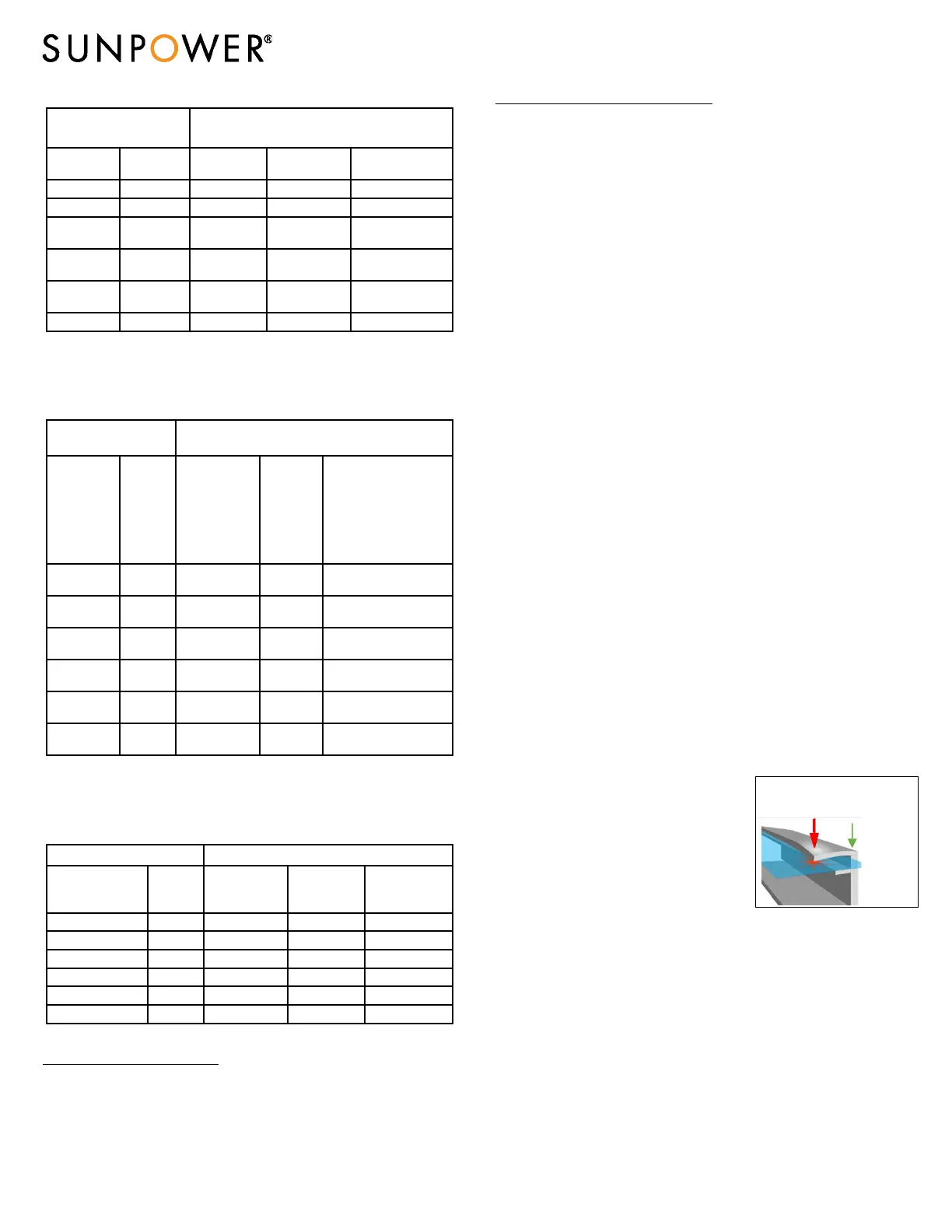
Clamps that secure to the top of the frame
must not deform the top flange. Clamps
must apply force collinear with the ‘wall’
of the module frame and not only to the
top flange. Clamps or installation procedures that put excessive force on the
top flange will deform the frame, void the module warranty and risk glass
breakage. Figure 1a illustrates locations for top frame clamp force. Do not
clamp within 50mm of module corners to reduce risk of frame corner
deflection and glass breakage. When clamping to the module frame, torque
should never exceed 120 in-lbs to reduce chances of frame deformation.
Maximum allowable torque may be less than 120 in-lbs depending on clamp
design. Mounting systems should be evaluated for compatibility before
installing.
3) End Mount: End mounting is the attachment of the shorter side of the
module frame to a supporting rail using IFF clips tightened to a torque of
35-45 in-lbs. The centerline of the clips must be 50-400mm from the corner
of the module. The end-mounting rail and clips or clamps must be of
sufficient strength to allow for the maximum design pressure of the
module. Verify this capacity before installation.
4)
Helix™ Mounting System: See UL2703 Helix system installation manual for
details.
Force must not deform
top frame flange or
glass may break
Figure 1a: Clamp Force Locations
Force can
be applied
in line with
frame wall
 Loading...