SUNPOWER CORPORATION
Safety and Installation Instructions - Document 001-14158 Rev AG
© 2020 SunPower Corporation. All rights reserved. Specifications included in these instructions are subject to change without notice. Page | 4
3) If the Unirac SOLARMOUNT system is used for mounting the modules,
grounding is achieved using either a BURNDY Wiley WEEB-UMC or WEEB-
UGC-1 grounding clip in combination with Unirac’s Mid or End clamps and
1/4-20 bolt and flanged nut, torqued to 120 in-lbs. If the SOLARMOUNT-I
system is used grounding is achieved with the Unirac UGC-2 grounding clips
in combination with Unirac’s Mid or End clamps and Sliders with a 1/4-20
bolt and flanged nut torqued to 120 in-lbs.
Note: Method 4 was evaluated to UL 2703 by TUV. As such, the use of these
devices is not considered part of the UL Listing of these modules.
4) SunPower modules may also be grounded using a WEEB-9.5NL ground clip in
between the module and supporting structure. This combination is secured
with a 1/4″ stainless steel rivet or a 1/4-20 by 3/4″ zinc-plated bolt with
zinc-plated K-nut torqued to min. 6 ft-lbs to secure the module to minimum
12 ga. G90 coated steel or Z-purlin, either painted or unpainted. The WEEB-
9.5NL is for single use only.
5) Other grounding methods may be used in conjunction with a module mounting
system tested to UL2703. For these installations, the SunPower module and
frame style must be tested and part of the instructions for the listed
mounting product. The SunPower module must be installed in accordance
with these instructions as well as the mounting system’s listed instructions.
6) SunPower G5-frame modules may be grounded through the use of an
InvisiMount mid clamp that bonds the module frame to the InvisiMount
rail. InvisiMount rail sections must be bonded and connected to a
grounding conductor using methods and materials specified in the
InvisiMount manual.
When using methods 2, 3, 4, 5 or 6 the module mounting structure must be
grounded as per NEC 250. To ensure system safety and structural integrity, strict
adherence to application-specific SunPower documentation is required.
4.2 System Grounding
Review Table 2 below for the proper grounding techniques for the installation of
your particular SunPower modules.
4.3 Series Connection
The modules may be wired in series to produce the desired voltage output. Do
not exceed the maximum system voltage shown in module datasheets and
product label.
4.4 Parallel Connection
The modules may be combined in parallel to produce the desired current output.
Each series string or module may be required to be fused prior to combining with
other strings if the resulting maximum fuse size allowed (number of modules
which can be connected in parallel and protected by one fuse) exceeds the fuse
rating as shown in the module datasheet and product label. Please refer to the
NEC Article 690 for additional fusing requirements.
Table 2: Module Grounding Key
Module Model Grounding Key
2
SunPower A-Series, P-Series, E-Series, X-Series,
MAX2, MAX3 and NE modules have no
grounding restrictions:
Legacy modules must be
positively grounded:
All model numbers
starting with “SPR-AZZZ”,
“SPR-AZZZ-BLK”, “SPR-
PYY”, “SPR-EYY”, “SPR-
XYY”, “SPR-MAX2”, or
“SPR-MAX3”.
SPR-ZZZNE-BLK-D
SPR-ZZZNE-WHT-D
SPR-ZZZE-WHT-D
SPR-ZZZ-WHT-D
SPR-ZZZE-BLK-D
SPR-ZZZ-BLK-D
IMPORTAN
! For optimal performance, SunPower modules listed above
as needing positive grounding must be configured as described. Failure to
comply with this requirement will reduce system performance and
invalidate SunPower’s Limited Power Warranty for PV Modules.
4.3 NEC 2017 690.12 Compliance
Modules containing -MLSD in the product name come with a pre-installed
SunSpec compliant rapid shutdown receiver from Tigo Energy Inc that, when used
2
YY is a number ranging from 15 to 22 and ZZZ is panel wattage.
and installed with approved equipment, constitute a UL1741 listed array meeting
the requirements of NFPA 70, 2017 article 690.12(B)(2). Please refer to Tigo
Energy’s list of approved equipment for additional details and requirements.
5.0 Module Mounting
The SunPower Limited Warranty for PV Modules is contingent upon modules
being mounted in accordance with the requirements described in this section.
5.1 Site Considerations
SunPower modules should only be mounted in locations that meet the following
requirements:
Operating Temperature: All SunPower modules must only be mounted in
environments that ensure they will operate within the following temperatures:
Operating Temperature range
-40°C to +85 °C
-40°F to +185 °F
Operating Temperature range (w/ MLSD)
-40°C to +75 °C
-40°F to +167 °F
Care should be taken to provide ventilation behind or underneath the modules,
especially in hot environments.
Design Strength: SunPower modules are designed to meet a maximum positive
(or up/down, e.g. wind) and negative (or downward, e.g. static or snow load)
design pressure described in the Table 3. Modules have also been evaluated by
UL for a maximum negative or positive design load of 30 psf. P19 modules have
been evaluated by UL for a maximum negative design load of 75 psf and
maximum positive design load of 125 psf.
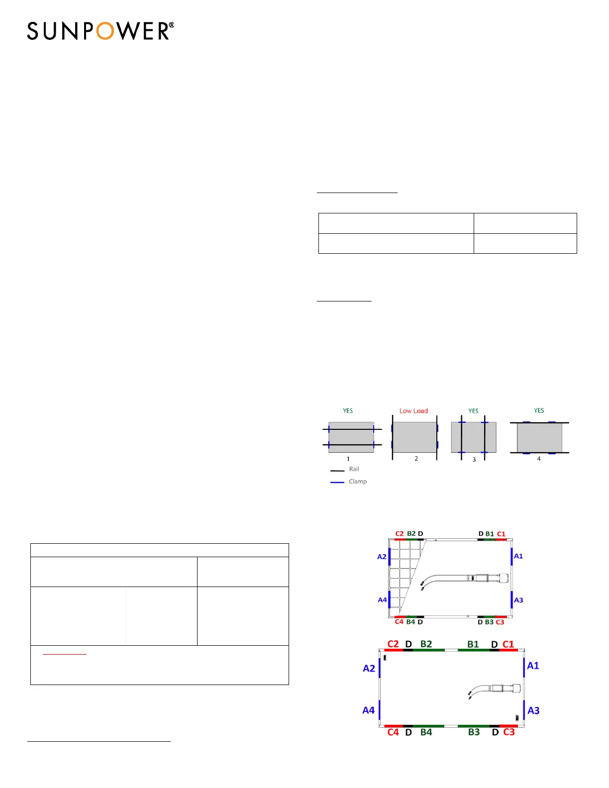
Figure 1: Mounting locations for SunPower Modules shows where to mount to
the module frame. Table 3 defines mounting options, attachment locations and
resulting load rating achieved for each module configuration.
Figure 1: Mounting locations for SunPower modules
Configurations 1 and 3 show mounting with rail support, 2 and 4 show mounting
without rail support.
For 96 cells, A-Series and 104c:
For 128 cells and P-Series:
 Loading...