www.sunred.nl
SAFETY
CAUTION: Before fitting or removing the appliance, ensure that the heater's power line supplying the heater is disconnected. Check that
the power line is connected to a 30mA differential circuit breaker.
■ This appliance is designed for use in gardens ,and any room in your house, including those where there is a risk of splashing. The
installation and use of your appliance must comply with the applicable standards in your country.
■ When it is switch on, an electrical heating appliance reaches very high temperature libel to cause burns. Make sure that all other
users are aware of the risks.
■ If you have any doubts concerning installation possibilities for this heater, please consult a qualified electrician.
■ Children, the elderly and the infirm may not always be aware of the danger involved in using electrical appliances. Never allow this
appliance to be used without supervision.
■ The appliance must be positioned so that the plug is accessible.
■ If the supply cord is damaged, it must be replaced by the manufacturer or its service agent or similar qualified person in order to
avoid a hazard
■ The heater must not be located immediately below a socket-outlet
■ Do not use this heater with a programmer, timer or any other device that switches the heater on automatically, since a fire risk exists
if the heater is covered or positioned incorrectly.
■ Do not place the appliance close to curtains and other combustible materials.
HOW TO ASSEMBLE
■ Before installing your appliance, you must disconnect the electrical supply at the circuit breaker.
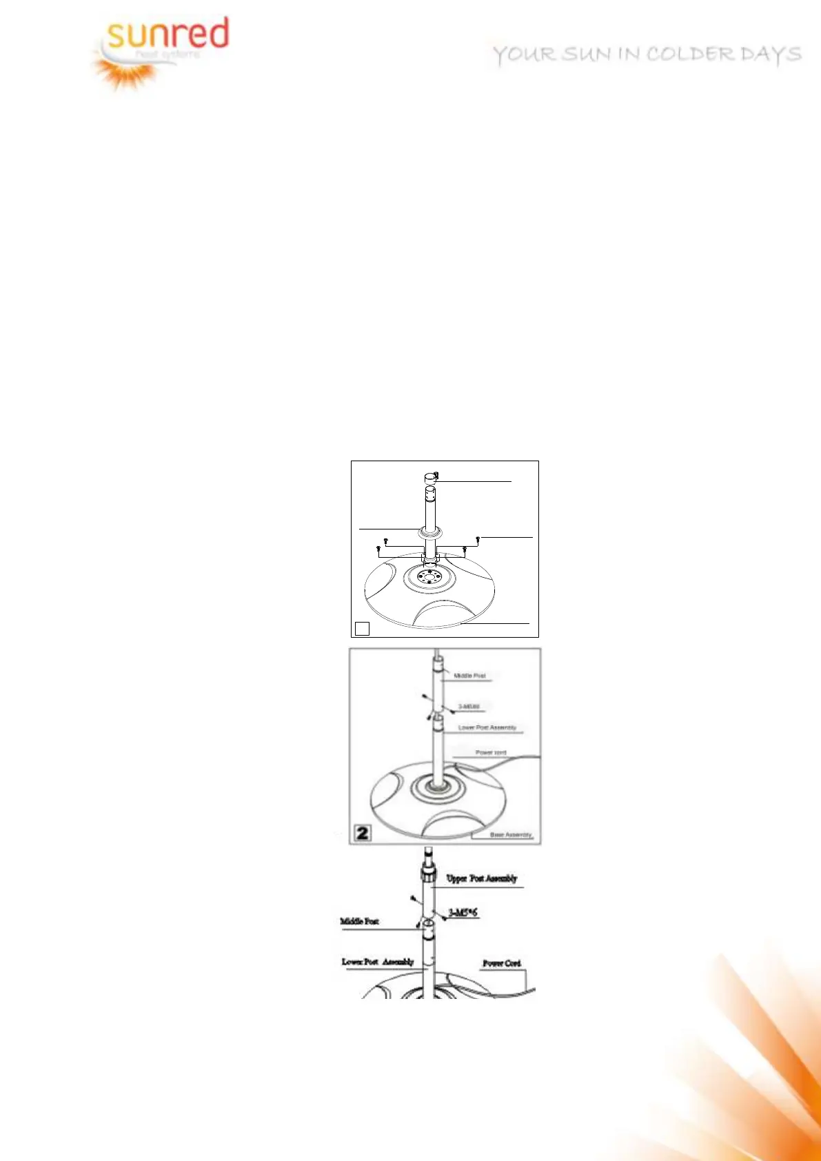
1 Insert the lower post assembly
(11) into the base assembly (16)
and then fix it tightly by means
of 4-M6X30 screw, and insert
the clamp (12) into the lower post
(11). (fig.1)
2 Join the Lower Post Assembly
(11) and the Middle Post (9)
together with 3-M5X6 screw
(fig.2)
3 Join the Upper Post Assembly
(7) and the Middle Post (9)
together with 3-M5X6.screw
(fig.3)
1
Clamp
4-M6 X 24 Screw
Lower Post Assembly
Base Assembly