Page 25 www.sunrotor.com
FIGURE 9-1 SUNROTOR
®
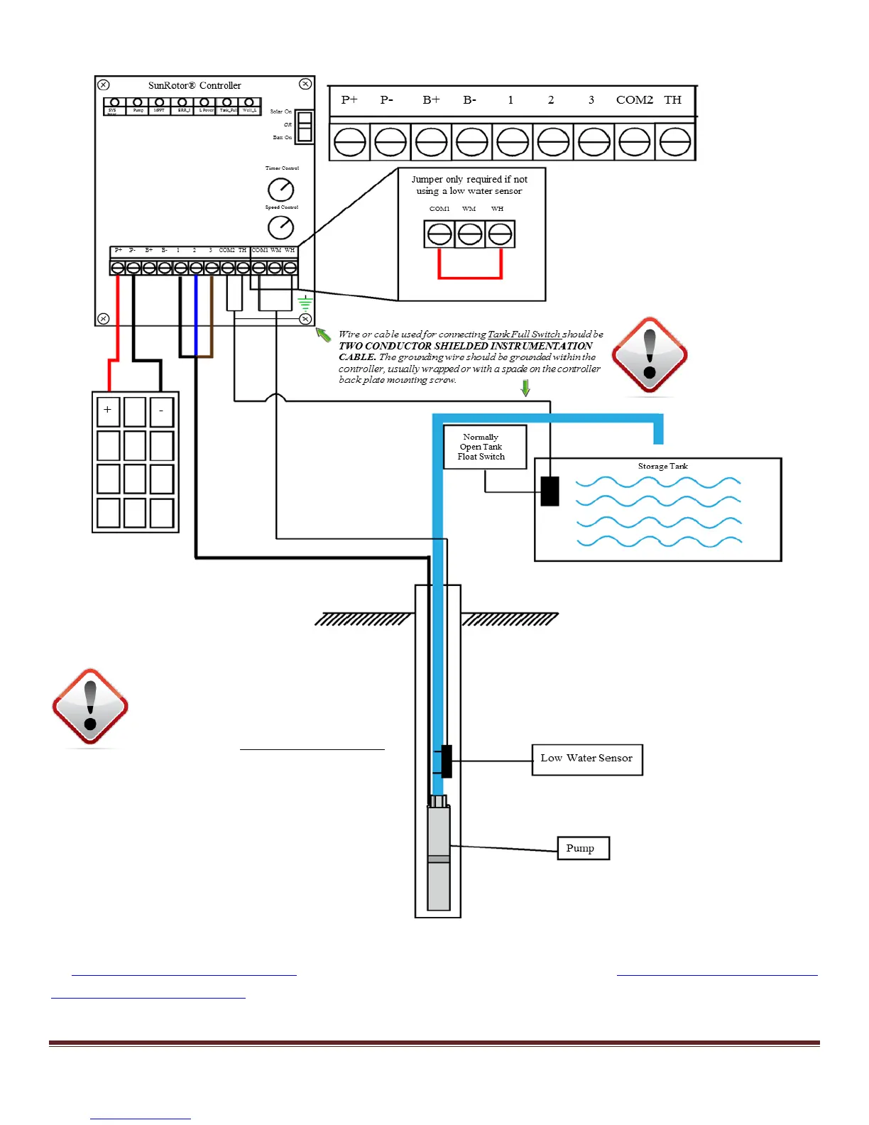
PUMP CONTROLLER WIRING DIAGRAM
Wire the pump cable into the controller. If the corresponding wires were written down as suggested
in Section 7.2 Splicing Your Wires, attach them accordingly; otherwise, use Figure 9-1 SunRotor
®
Pump
Controller Wiring Diagram to wire the pump properly (typically terminal 1: black; terminal 2: blue;
terminal 3: brown on most SunRotor
®
model solar pumps). If unsure, attach the pump wires to any
SunRotor® Submersible pumps have a
strict submergence limit of 100 FT.
Exceeding this depth could damage the
pump and will VOID THE WARRANTY.