- 8 -
SXJS3018 DOUBLE-DECK SCISSOR LIFT
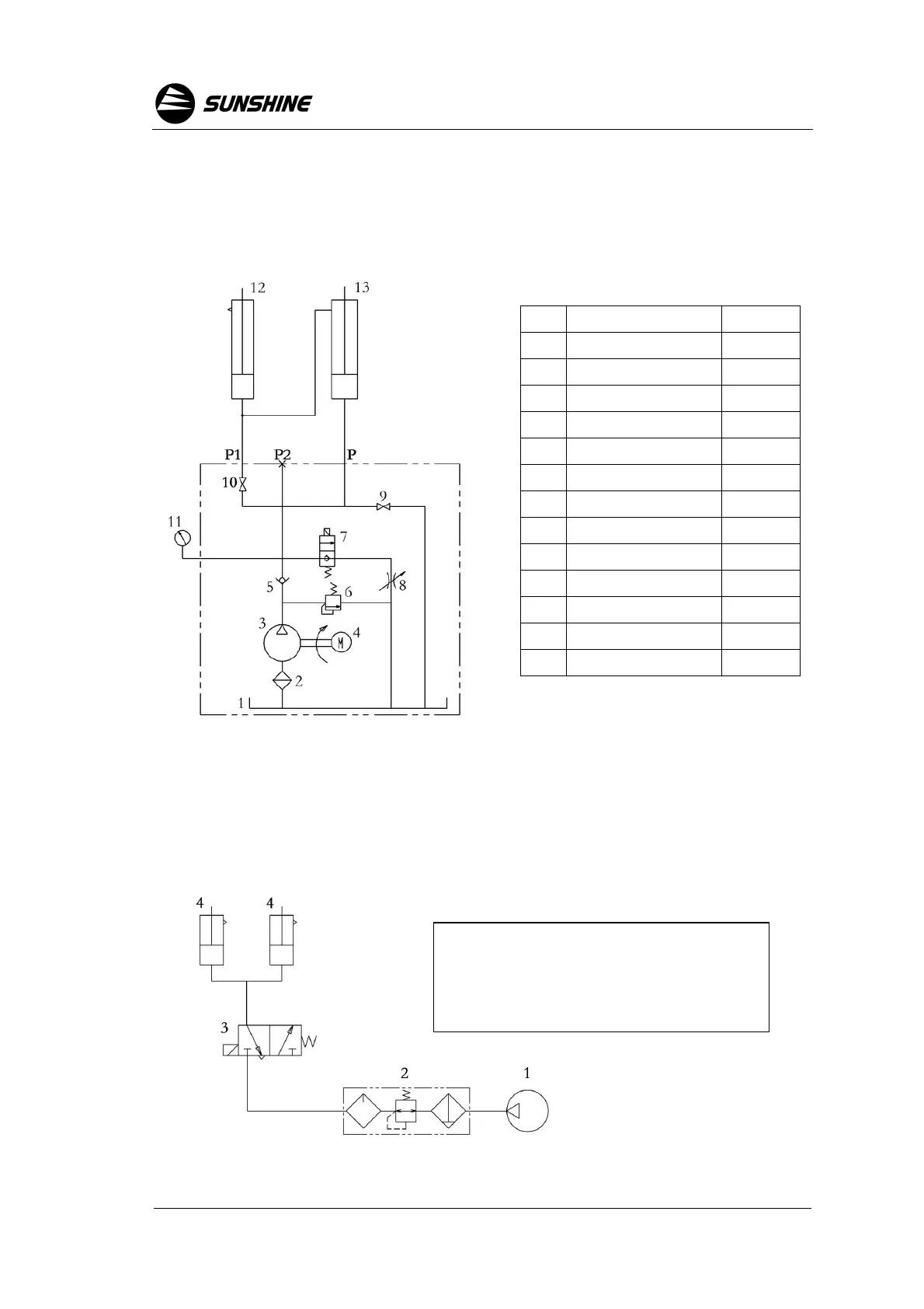
Fig. 7 Pneumatic system schematic
valve is adjusted well in factory, it’s forbidden to adjust than the rated load.)
4.2 When you use the lift first time after installation, pay attention to the
direction of motor rotation while connecting wires. If the motor is rotating in the
wrong direction for too long time, the gear pump could be damaged.
Fig. 6 Hydraulic system diagram
Chapter 5. Pneumatic System
The connection of the pneumatic system refer to Fig. 4. The schematic of the
pneumatic system refer to Fig. 7.
No.
Name Remark
1 Oil tank
2 Purolator
3 Lubricant pump
4 Motor
5 Retaining valve
6 Relief valve
7 Unloading valve
8 Throttle valve
9 Cut-off valve
10 Cut-off valve
11 Hydraulic gauge
12 Vice-cylinder
13 Main cylinder
1. Air Compressor (customer self-provided)
2. Pneumatic FRL
3. Air Valve