RETROREFLECTIVE TYPE SEN-
SOR WITH POLARIZING FILTERS
(CX-491š)
8
٨ As light is polarized by a transparent film or mem-
brane, CX-491غ may not detect an object covered
or wrapped by transparent film. In that case, take
the following measures.
<Example of sensing objects>
Can wrapped by clear film
Aluminum sheet covered by plastic film
Gold or silver color (glossy) labels or wrapping
paper
<Measures>
Tilt the sensor with respect to the sensing object
upon fitting.
Reduce the sensitivity.
Increase the distance between the sensor and the
sensing object.
How to mount
SLIT MASK (OPTIONAL)
(Exclusively for thru-beam type sensor)
9
٨ With the slit mask (OS-CX-غ), the sensor can
detect a small object.
However, the sensing range is reduced when
the slit mask is mounted.
Ԙ
ԙ
Insert the fixing hook into the fixing groove.
Then, pressing the slit mask against the main
unit, insert the fixing tab into the fixing groove.
Ԙ
ԙ
Insert a screwdriver into the removing tab.
Pull forward while lifting the removing tab.
How to remove
Type Model No. Slit size
Round slit mask
OS-CX-05 Ǿ0.5mm
OS-CX-1 Ǿ1mm
OS-CX-2 Ǿ2mm
Rectangular slit
mask
OS-CX-05g6 0.56mm
OS-CX-1g6 16mm
OS-CX-2g6 26mm
Fixing groove
Fixing tab
Removing tab
Slit mask
Fixing groove
Fixing hook
INTERFERENCE PREVEN-
TION FILTER (OPTIONAL)
(Exclusively for CX-411š)
10
٨
٨
٨
By mounting the interference prevention filters
(PF-CX4-غ), two sets of the CX-411غ can be
mounted close together.
However, the sensing range is reduced when
the interference prevention filter is mounted.
The filters can be mounted by the same method
as for the slit masks.
Since there are two types of the interference
prevention filter, the two sets of sensors should
be fitted with different types of interference pre-
vention filters, as shown in the figure below.
The interference prevention does not work even
if the filters are mounted for emitters only, re-
ceivers only or the same model No. of the inter-
ference prevention filters are mounted on both
the sets of the sensor.
Fitted with
PF-CX4-H
Fitted with
PF-CX4-V
٨ Sensitivity adjustment
Note: Use the 'minus' adjusting screwdriver (please arrange sepa-
rately) to turn the adjuster slowly. Turning with excessive
strength will cause damage to the adjuster.
Ԙ
ԙ
Ԛ
ԛ
Turn the sensitivity adjuster fully counter-
clockwise to the minimum sensitivity posi-
tion, MIN.
In the light received condition, turn the sensitivity
adjuster slowly clockwise and confirm the point
where the sensor enters the 'Light' state operation.
In the dark condition, turn the sensitivity ad-
juster further clockwise until the sensor en-
ters the 'Light' state operation and then bring
it back to confirm point where the sensor
just returns to the 'Dark' state operation.
If the sensor does not enter the 'Light' state
operation even when the sensitivity adjuster is
turned fully clockwise, the position is point .
The position at the middle of points and
is the optimum sensing position.
Step
Sensitivity adjuster
Description
Optimum position
Diffuse
reflective
Thru-beam
Retroreflective
Light received condition Dark condition
Emitter Receiver
Sensing
object
Sensor
Sensor Reflector
Emitter Receiver
Sensing
object
Sensor
Sensing
object
Sensor Reflector
Relation between output and indicators
In case of Light-ON In case of Dark-ON
: Lights up,
: Turns off
Stable light
receiving
Stable dark
receiving
Unstable light
receiving
Unstable dark
receiving
Stability
indicator
Operation
indicator
Output
ON OFF
OFF ON
Stability
indicator
Operation
indicator
Output
Sensing
condition
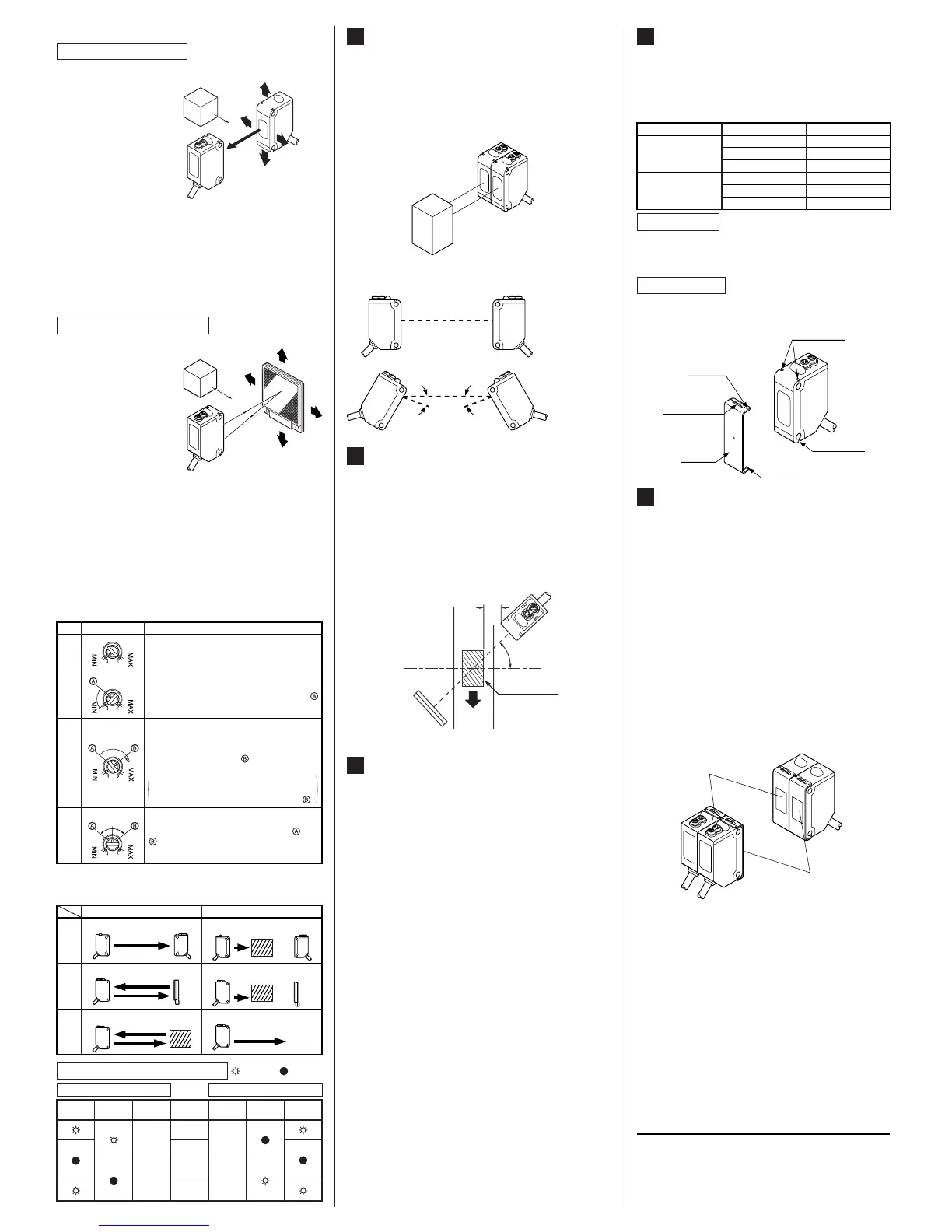
LONG SENSING RANGE RET-
ROREFLECTIVE TYPE SENSOR
(CX-493š)
7
٨ Please take care of the following points when
detecting materials having a gloss.
Ԙ
ԙ
Make 'L', shown in the diagram, sufficiently
long.
Install at an angle of 10 to 30 degrees to the
sensing object.
* CX-491غ do not need the above adjustment.
L
10 to 30q
Sensing
object
Reflector
Glossy surface
SUNX Limited
٨ Beam alignment
Ԙ
ԙ
Ԛ
ԛ
Ԝ
ԝ
Set the operation mode switch to the Light-ON mode
position (L side).
Placing the emitter
and the receiver face
to face along a straight
line, move the emitter
in the up, down, left
and right directions, in
order to determine the
range of the light re-
ceived condition with
the help of the operation indicator (orange).
Then, set
the emitter at the center of this range.
Similarly, adjust for up, down, left and right angular
movement of the emitter.
Further, perform the angular adjustment for the re-
ceiver also.
Check that the stability indicator (green) lights up.
Choose the operation mode, Light-ON or Dark-ON, as
per your requirement, with the operation mode switch.
Sensing object
Emitter
Receiver
Thru-beam type sensor
Ԙ
ԙ
Ԛ
ԛ
Ԝ
ԝ
Set the operation mode switch to the Light-ON mode
position (L side).
Placing the sensor
and the reflector
face to face along a
straight line, move
the reflector in the
up, down, left and
right directions, in
order to determine
the range of the
light received condition with the help of
the operation indicator (orange). Then, set the re-
flector at the center of this range.
Similarly, adjust for up, down, left and right angular
movement of the reflector.
Further, perform the angular adjustment for the
sensor also.
Check that the stability indicator (green) lights up.
Choose the operation mode, Light-ON or Dark-ON, as
per your requirement, with the operation mode switch.
Retroreflective type sensor
Reflector
Sensor
AUTOMATIC INTERFERENCE
PREVENTION FUNCTION
(Excluding thru-beam type sensor)
6
Note: If two diffuse reflective type sensor are mounted facing each
other, they should be angled so as not to receive the beam
from the opposing sensor or to detect its front face.
٨ Retroreflective type sensor and diffuse reflective
type sensor incorporate this function. Up to two
sets of sensor can be mounted closely.
(Thru-beam type sensor does not have this function.)
Close mounting of two sensors
No good
ǰ ǰ
Good
 Loading...